Serial Communications
Overview The SMC Dialog Plus™ controller can be started, stopped, and programmed
through PLCs or SLCs using an optional Bulletin 1203 communication
module. Additionally, parameter data can be read to the logic controller
through block transfer. The amount of information that can be transferred
from the SMC Dialog Plus controller is determined by the DIP switch
settings on the communication module.
Note: Parameter values modified while the motor is operating are not
valid until the next start sequence begins.
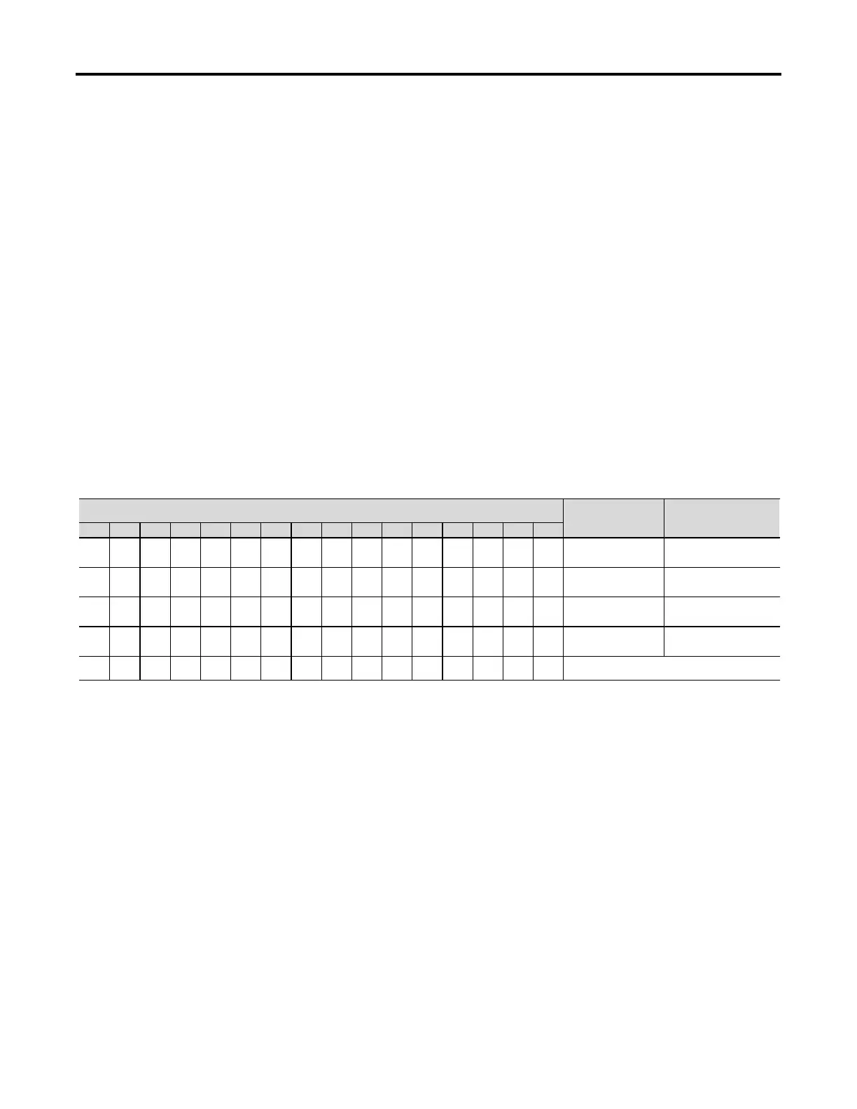
Logic Control Data The information in Table 8.A provides the logic control information that
can be sent to the SMC Dialog Plus controller through the logic controller's
output image table.
Logic Bits
1514131211109876543210
Description Definition
X Stop
1 = Stop
0 = Not Stopped
XStart
1 = Start
0 = Not Start
X Option Command
1 = Option Init.
0 = Not Option Init.
X Clear Faults
1 = Clear Faults
0 = Not Clear Faults
Bits 4-15 are not used
Only one bit may be asserted at any given time.
The stop bit will take priority when more than one bit is asserted. Other bits will be ignored until the stop bit is reset.
A 0 to 1 transition is required for a valid command.
Table 8.A – Logic Control Data
Control Wiring Refer to Figure 1.18(c) or 1.18(d) on pages 1-24 and 1-25 respectively for
the applicable wiring diagram to achieve start-stop control via the
SCANport.
Chapter 8
1560D-UM051D-EN-P – February 2005
 Loading...


