10-10 Troubleshooting
1560D-UM051D-EN-P – February 2005
IGDPS Board LEDs A green LED is provided inside each of the six (6) output module boxes
(channels) to indicate the presence of a healthy output voltage (20 V DC).
• LED ON: Output Healthy
• LED OFF: Output Voltage is below 18 V DC
If the IGDPS is healthy, then all six (6) LEDs will be illuminated. If this is
not true, this may indicate either a bad connection to the board or a
defective output module. If all six (6) LEDs are not illuminated, measure
the input power to the IGDPS board(s). It should be 50 V DC, ± 8 V DC.
Record the following measurements to ensure all six (6) outputs are
functioning. They should be within ±1% of 20 V.
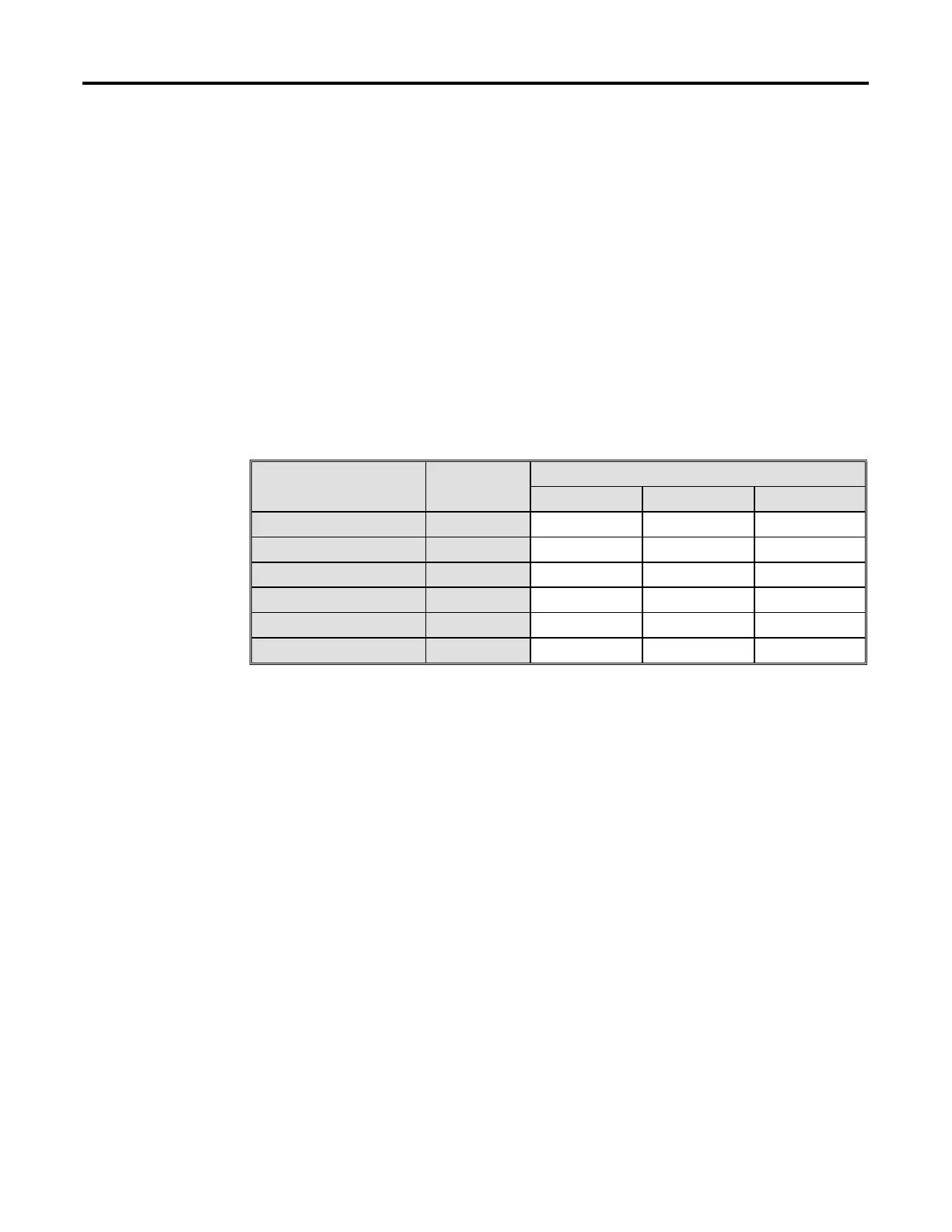
Table 9.G – Test Point Measurement Values
Measured Value
Test Points
Expected
Value
Board #1 Board #2 Board #3
Channel 1 - Pin 1 Æ Pin 2 +20 V DC
Channel 2 - Pin 1 Æ Pin 2 +20 V DC
Channel 3 - Pin 1 Æ Pin 2 +20 V DC
Channel 4 - Pin 1 Æ Pin 2 +20 V DC
Channel 5 - Pin 1 Æ Pin 2 +20 V DC
Channel 6 - Pin 1 Æ Pin 2 +20 V DC
There may be more than one IGDPS board. Record output voltages for all
of them.
 Loading...


