Installation 2-15
1560D-UM051D-EN-P – February 2005
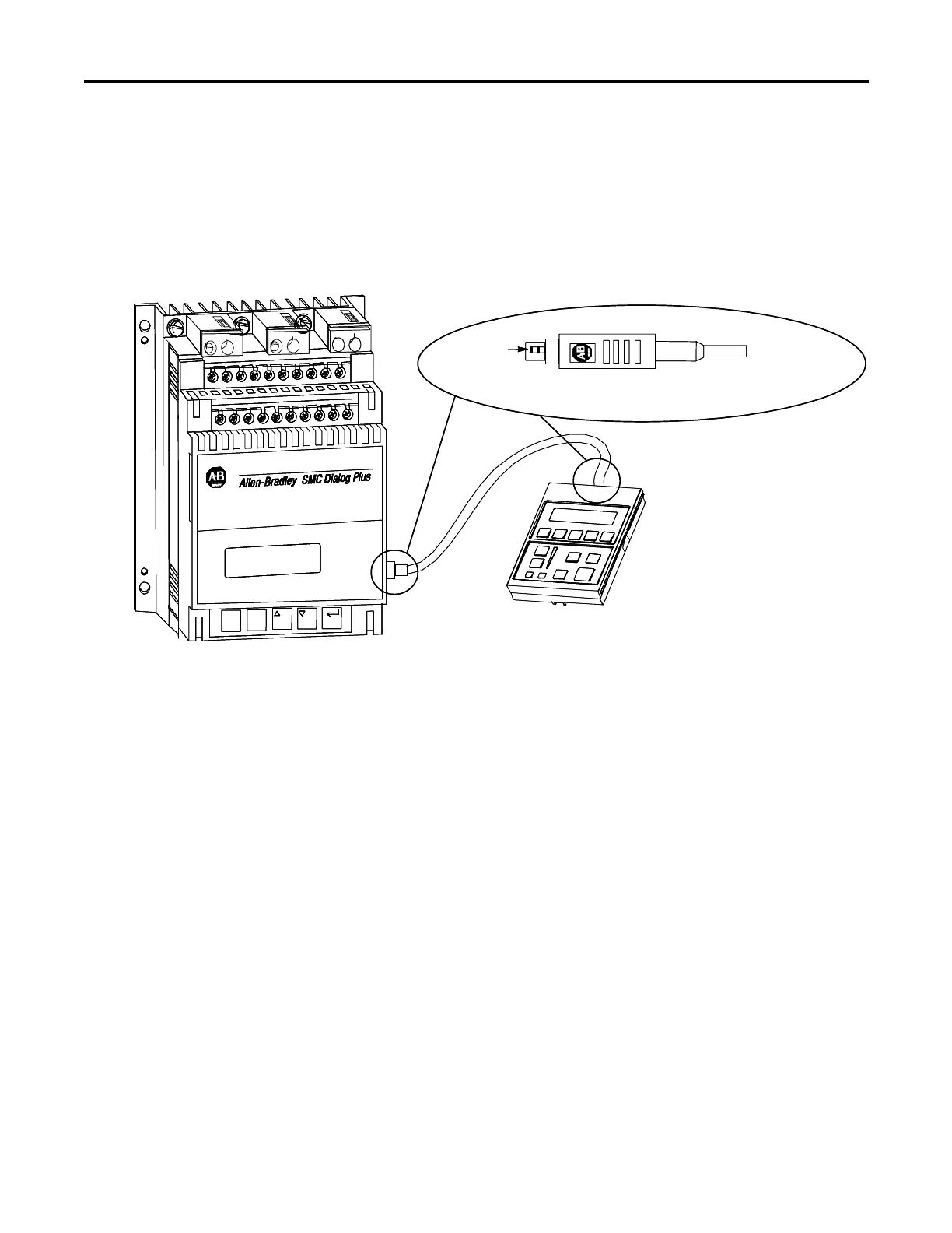
Connecting the Human Interface Module to the Controller
Figure 2.5 shows the connection of the SMC Dialog Plus controller to a
human interface module. See Figure 1.20 or 1.21 on page 1-25 or 1-26 for
the control wiring diagram that enables start-stop control from a human
interface module.
Human Interface Module
Latching
Mechanism
23
14
24
15
25
16
26
17
27
18
28
19
29
20
30
3
5
ESC. SEL.
L1
L2
L3
1
11
21
12
22
13
Pull back moving part (connector body)
to disconnect cable from the SCANport connection.
Bulletin 1202 Cable
SMC Dialog Plus Controller
Human Interface Module
Latching
Mechanism
23
14
24
15
25
16
26
17
27
18
28
19
29
20
30
3
5
ESC. SEL.
L1
L2
L3
1
11
21
12
22
13
23
14
24
15
25
16
26
17
27
18
28
19
29
20
30
3
5
ESC. SEL.
L1
L2
L3
1
11
21
12
22
13
Pull back moving part (connector body)
to disconnect cable from the SCANport connection.
Bulletin 1202 Cable
SMC Dialog Plus Controller
Figure 2.5 – SMC Dialog Plus Controller with Human Interface Module
 Loading...


