Serial Communications 8-37
1560D-UM051D-EN-P – February 2005
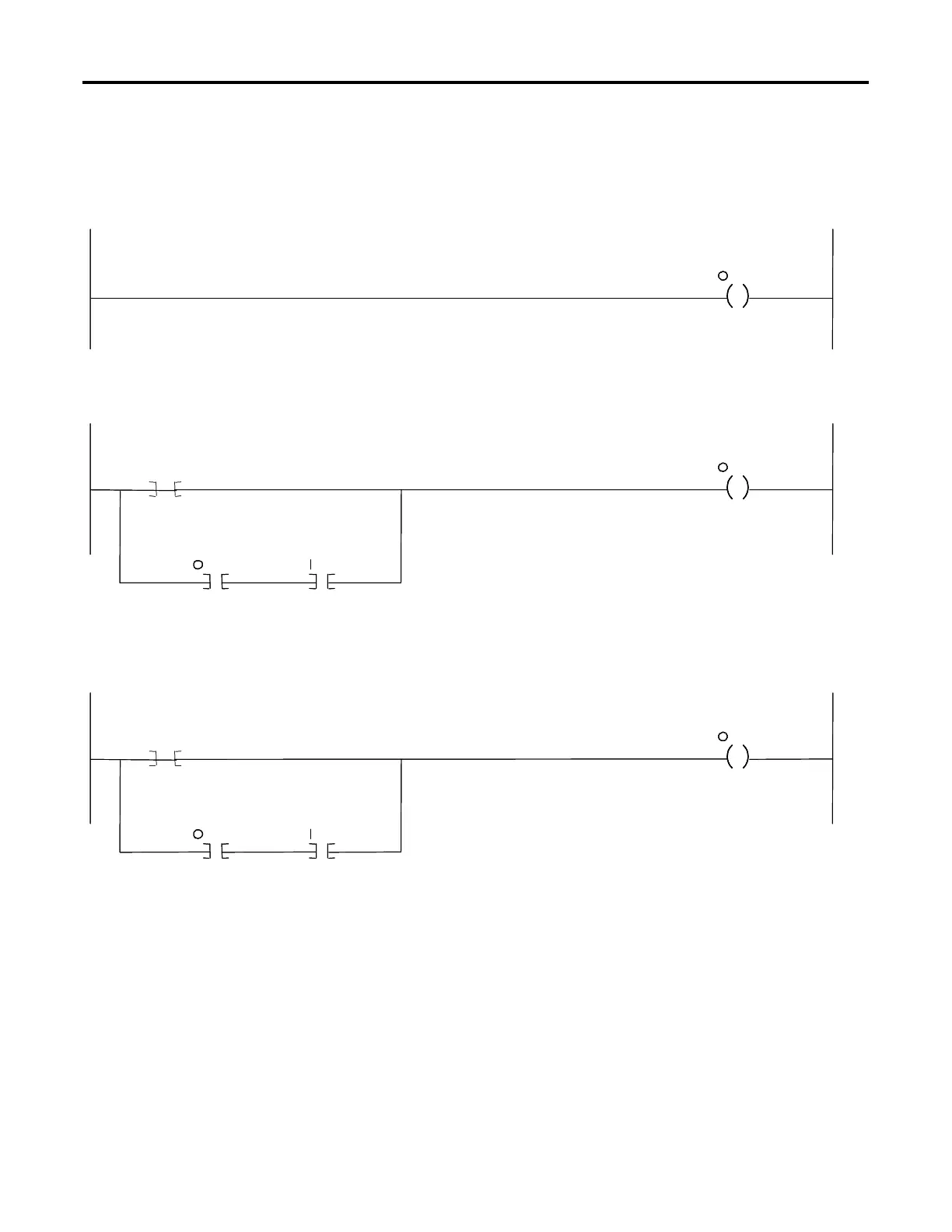
Example Ladder Logic Program
1747-SDN
Enable
Bit
: 1
0
Start CMD
From
RSVIEW
B3
SMC
START
Command
: 1.7
Rung 0: The 1747-SDN scanner module will map output data from its scanner output table (MO) and discrete outputs to each node only when
it’s in the “run mode”. This is accomplished by setting bit 0 of the 1747-SDN’s command word (word 0).
11
1
Rung 1: When the START command is initiated at the RSView station the SLC processor sets the output bit mapped to the SMC Dialog Plus Controller’s logic
control word start bit. The branch provides a logic “latched” circuit which exerts the START command until input from the SMC Dialog Plus controller’s status word
indicates that it has received the command and has responded appropriately. The SMC Dialog Plus controller will start if no STOP command is being issued by
the SLC or any other control device.
SMC
START
Command
: 1.7
SMC
Running
Bit
: 1.7
Stop CMD
From
RSVIEW
B3
SMC
STOP
Command
: 1.7
01
1
Rung 2: When the STOP command is initiated at the RSView station the SLC processor sets the output bit mapped to the SMC Dialog Plus controller’s logic
control word stop bit. The branch provides a logic “latched” circuit which exerts the STOP command until input from the SMC Dialog Plus controller’s status
word indicates that it has received the command and has responded appropriately.
SMC
STOP
Command
: 1.7
SMC
Running
Bit
: 1.7
 Loading...


