8-38 Serial Communications
1560D-UM051D-EN-P – February 2005
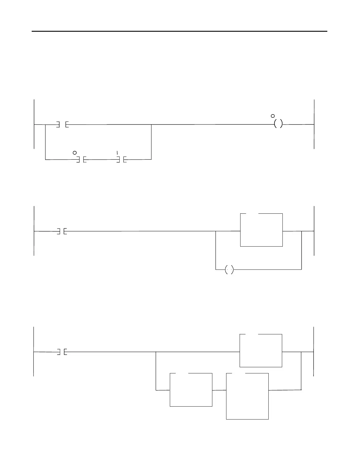
Example Ladder Logic Program (cont.)
Initiate
Explicit
Message
B3
Explicit
Message
Request
Rung 3: When the FAULT RESET command is initiated at the RSView station, the SLC processor sets the output bit mapped to the SMC Dialog Plus
controller’s logic control word clear faults bit. The branch provides a logic “latched” circuit which exerts the FAULT RESET command until input from the
SMC Dialog Plus controller’s status word indicates that ti has received the command and has responded appropriately. The SMC Dialog Plus controller’s
CLEAR FAULT bit functions as long as all other logic control bits have been reset to zero.
Rung 4: When bit B3:0/0 is set, the 32 words beginning at N11:0 from the SLC processor are copied to the 1747-SDN scanner’s M0 file. The 1747-SDN
scanner sends this message out over the DeviceNet trunkline. The unlatch branch instruction resets B3:0/0 to zero for the next processor scan.
Rung 5: When the 1747-SDN scanner has an Explicit Message response available, it sets bit 15 of its status word (I:1/15 in this example). The Explicit
Message response is then copied from the 1747-SDN scanner’s M1 file to the SLC processor’s N11 file, beginning at word 50. The branch copies a command
byte of 4 into the 1747-SDN scanner’s M0 file which directs it to discard the response data to prepare it for the next Explicit Message operation.
FAULT RESET
From
RSVIEW
B3
CLEAR FAULT
Command
: 1.7
3
SMC
CLEAR FAULT
Command
: 1.7
SMC
FAULT
Bit
: 1.7
SMC
275
3
7
COP
Copy File
Source N11:0
Dest M0:1.224
Length 32
0
B3
U
0
Explicit
Message
Response
Available
I : 1
Explicit
Message
Response
COP
Copy File
Source M1:1.224
Dest N11:50
Length 32
15
EQU
Equal
Source A N11:0
257<
Source B N11:50
257<
MVM
Masked Move
Source N11:0
4<
Mask 00FFh
255<
Dest M0:1.224
? <
Initiate
Explicit
Message
B3
Explicit
Message
Request
Explicit
Message
Request
Rung 3: When the FAULT RESET command is initiated at the RSView station, the SLC processor sets the output bit mapped to the SMC Dialog Plus
controller’s logic control word clear faults bit. The branch provides a logic “latched” circuit which exerts the FAULT RESET command until input from the
SMC Dialog Plus controller’s status word indicates that ti has received the command and has responded appropriately. The SMC Dialog Plus controller’s
CLEAR FAULT bit functions as long as all other logic control bits have been reset to zero.
Rung 4: When bit B3:0/0 is set, the 32 words beginning at N11:0 from the SLC processor are copied to the 1747-SDN scanner’s M0 file. The 1747-SDN
scanner sends this message out over the DeviceNet trunkline. The unlatch branch instruction resets B3:0/0 to zero for the next processor scan.
Rung 5: When the 1747-SDN scanner has an Explicit Message response available, it sets bit 15 of its status word (I:1/15 in this example). The Explicit
Message response is then copied from the 1747-SDN scanner’s M1 file to the SLC processor’s N11 file, beginning at word 50. The branch copies a command
byte of 4 into the 1747-SDN scanner’s M0 file which directs it to discard the response data to prepare it for the next Explicit Message operation.
FAULT RESET
From
RSVIEW
B3
CLEAR FAULT
Command
: 1.7
3
SMC
CLEAR FAULT
Command
: 1.7
SMC
FAULT
Bit
: 1.7
SMC
275
3
7
COP
Copy File
Source N11:0
Dest M0:1.224
Length 32
0
B3
U
0
Explicit
Message
Response
Available
I : 1
Explicit
Message
Response
Explicit
Message
Response
COP
Copy File
Source M1:1.224
Dest N11:50
Length 32
15
EQU
Equal
Source A N11:0
257<
Source B N11:50
257<
MVM
Masked Move
Source N11:0
4<
Mask 00FFh
255<
Dest M0:1.224
? <
 Loading...


