3-6 Commissioning Procedures
1560D-UM051D-EN-P – February 2005
Power Supply Tests Servicing energized industrial control equipment can be
hazardous. Severe injury or death can result from
electrical shock, burn, or unintended actuation of
controlled equipment. Before proceeding, ensure that all
sources of power are isolated and locked out. Verify that
all circuits are voltage free using a hot stick or appropriate
voltage measuring device. Any covers or barriers
removed during this procedure must be replaced and
securely fastened before energizing equipment. Where
appropriate, the case of test equipment should be
connected to ground.
1. Isolate incoming power
2. Open the door(s) providing access to the SCR/heatsink assemblies.
You will be touching components which are connected to the high
voltage power circuit, so be sure to isolate power as stated above.
3. Apply rated control voltage to the control circuits from a separate
control source, or by plugging into the test source connector, and
selecting the TEST position of the control switch.
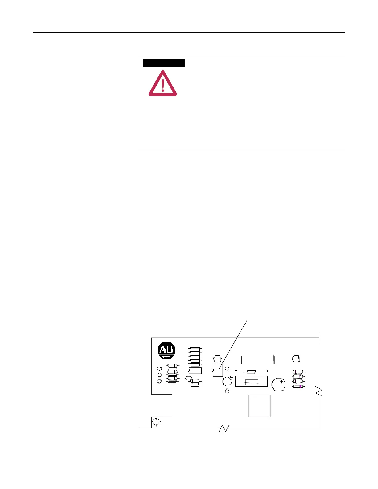
4. Locate the MV Dialog Interface board in the control section (See
Figure 3.2). This circuit board has the black control module mounted on
it. Locate the switch labeled DIP1 at the upper left corner of the board.
Close the switch by sliding the toggle up. This starts a pulse generator
to supply simulated gate-pulse signals via fibre optic cables to the gate
driver boards. LED 2 (red) above the switch, and the three yellow
LEDs (LED 3, 4, 5) on the left side of the Interface board should be lit.
(Note: They may appear dim, depending on ambient light conditions).
Close switch to activate test pulses.
LED2 indicates pulses are activated.
LED2
DIP1
MADE IN CANADA
Close switch to activate test pulses.
LED2 indicates pulses are activated.
LED2
DIP1
MADE IN CANADA
Figure 3.2 – Interface PCB
A T T E N T I O NA T T E N T I O N
 Loading...


