Commissioning Procedures 3-5
1560D-UM051D-EN-P – February 2005
POWER
L
N
G
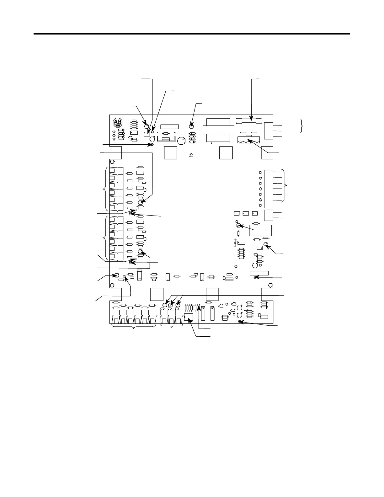
DIP 1: Pulse – Turn ON (slide up) to
apply test pulses to gate drive circuits.
NOTE: Must be OFF for normal operation.
LED 2 (Red): Pulse – ON
when test pulses on.
Test Point 1 (COM)
LED 3 (Yellow): Phase A
ON when gate signal present
Phase A Fibre Optic Transmitters.
Send gate signals to gate driver
board via fibre optic cables.
All transmitters within a phase
are in series and are driven
simultaneously. (See note 2)
Test Point 1 (COM)
Test Point 10:
Phase A Gate Signal
Phase B Fibre Optic Transmitters
(See note 2)
Test Point 11:
Phase B Gate Signal
Test Point 1 (COM)
LED 4 (Yellow) ON when
Phase B gate signal present
LED 5 (Yellow) ON when
Phase C gate signal present
Test Point 12:
Phase C Gate Signal
Phase C Fibre Optic
Transmitters
(See note 2)
Temperature
feedback fibre
optic receivers.
One cable from a
gate driver board
in each phase.
Test Point 3: +5 V
DIP 2: Use to defeat individual or all temperature feedback channels.
Switch 4 must be OFF for normal operation. If there are fibre optic
cables present in the blue receivers to the left, the corresponding
switch(es) must be OFF (press in at bottom to turn off). If a blue
receiver does not have a cable plugged in, the corresponding switch
must be ON.
Test Point 1 (COM)
LED 8, LED 9, LED 10 (Green)
ON when signal present at
temperature feedback fibre
optic receiver(s).
Test Point 1 (COM)
LED 6 (Red): UTS status.
ON when Dialog UTS signal
is true.
LED 7 (Red): VF inhibit.
ON when voltage feedback
signals are inhibited.
UTS: Dialog Term. 19
Control Common
Motor voltage inputs
from voltage feedback
board
Voltage Selection Plug (TB2):
Apply jumpers per rated
control voltage range.
NEUTRAL
GROUND
LINE
Control Power:
100-120 or 220-240 VAC
50 or 60 Hz
Control Fuse (F1): Replace with
Indicated size and type, depending on
rated control voltage.
Part Numbers: 1/10A – 80174-028-02
1/16A – 80174-028-01
LED 1 (Green): Power
ON when control power
applied.
Test Point 2:
+12 V
POWER
L
N
G
DIP 1: Pulse – Turn ON (slide up) to
apply test pulses to gate drive circuits.
NOTE: Must be OFF for normal operation.
LED 2 (Red): Pulse – ON
when test pulses on.
Test Point 1 (COM)
LED 3 (Yellow): Phase A
ON when gate signal present
Phase A Fibre Optic Transmitters.
Send gate signals to gate driver
board via fibre optic cables.
All transmitters within a phase
are in series and are driven
simultaneously. (See note 2)
Test Point 1 (COM)
Test Point 10:
Phase A Gate Signal
Phase B Fibre Optic Transmitters
(See note 2)
Test Point 11:
Phase B Gate Signal
Test Point 1 (COM)
LED 4 (Yellow) ON when
Phase B gate signal present
LED 5 (Yellow) ON when
Phase C gate signal present
Test Point 12:
Phase C Gate Signal
Phase C Fibre Optic
Transmitters
(See note 2)
Temperature
feedback fibre
optic receivers.
One cable from a
gate driver board
in each phase.
Test Point 3: +5 V
DIP 2: Use to defeat individual or all temperature feedback channels.
Switch 4 must be OFF for normal operation. If there are fibre optic
cables present in the blue receivers to the left, the corresponding
switch(es) must be OFF (press in at bottom to turn off). If a blue
receiver does not have a cable plugged in, the corresponding switch
must be ON.
Test Point 1 (COM)
LED 8, LED 9, LED 10 (Green)
ON when signal present at
temperature feedback fibre
optic receiver(s).
Test Point 1 (COM)
LED 6 (Red): UTS status.
ON when Dialog UTS signal
is true.
LED 7 (Red): VF inhibit.
ON when voltage feedback
signals are inhibited.
UTS: Dialog Term. 19
Control Common
Motor voltage inputs
from voltage feedback
board
Voltage Selection Plug (TB2):
Apply jumpers per rated
control voltage range.
NEUTRAL
GROUND
LINE
Control Power:
100-120 or 220-240 VAC
50 or 60 Hz
Control Fuse (F1): Replace with
Indicated size and type, depending on
rated control voltage.
Part Numbers: 1/10A – 80174-028-02
1/16A – 80174-028-01
LED 1 (Green): Power
ON when control power
applied.
Test Point 2:
+12 V
NOTES:
1. All test point voltages or signals are relative to TP1 (COM) except TP6 “TEMP MODULE” which is relative to TP19 “TEMP COM” only.
TP19 must not be connected to ground or TP1 “COM”. There are several TP1 locations on the board for convenience.
2. There are two versions of the circuit board: -51 and -53 have four fibre optic transmitters per phase (for <2700 volt operation, only two
per phase will be utilized); -52 and -54 have six fibre optic transmitters per phase for >5000 volt operation.
3. Part numbers 80187-131-51 and -52 are factory set for 100-120 VAC control power. 80187-131-53 and -54 are factory set for 220-240 VAC
control power. They can be changed in the field by moving the jumpers on the voltage selection plug (TB2) and changing the fuse (F1).
Figure 3.1 – Connection and Test Information for Interface Board
 Loading...


