10-8 Troubleshooting
1560D-UM051D-EN-P – February 2005
The most straightforward means of checking the feedback circuits is to
perform the "snubber and resistor testing" procedure, found on page 10-24.
Another possible test involves measuring the feedback voltages at the
interface board (see Figure 1.17). This can only be done with line voltage
applied. If the motor does not start, it may be necessary to temporarily
modify the control circuit to close the line contactor without applying a
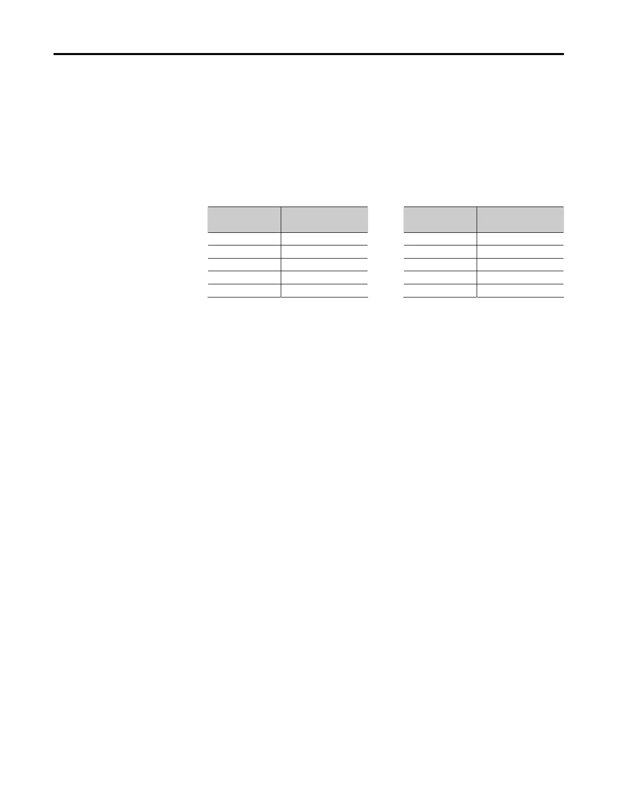
start signal to the Dialog module. In this case, the three line voltages (L1,
L2, L3) measured with respect to ground should be as follows:
System Voltage
(V
LL
)
Feedback Voltage
(V
LG
)
System Voltage
(V
LL
)
Feedback Voltage
(V
LG
)
1000 210 – 230 4160 177 – 197
1300 210 – 230 4800 206 – 226
1500 171 – 191 6600 195 – 215
2400 191 – 211 5500 180 – 200
3300 205 – 225 6900 204 – 224
If any voltage is well outside this range, there may be a problem either with
the system voltage, or with the voltage divider for the affected phase. Note
that the load side voltages (T1, T2, T3) will be very low, since the SCRs
are not turned on, and only a low leakage current flows to the motor.
If the motor will start and run, the line and load voltages should be the
same when the bypass contactor is closed.
Voltage Feedback Circuit
Tests
 Loading...


