Installation 2-21
1560D-UM051D-EN-P – February 2005
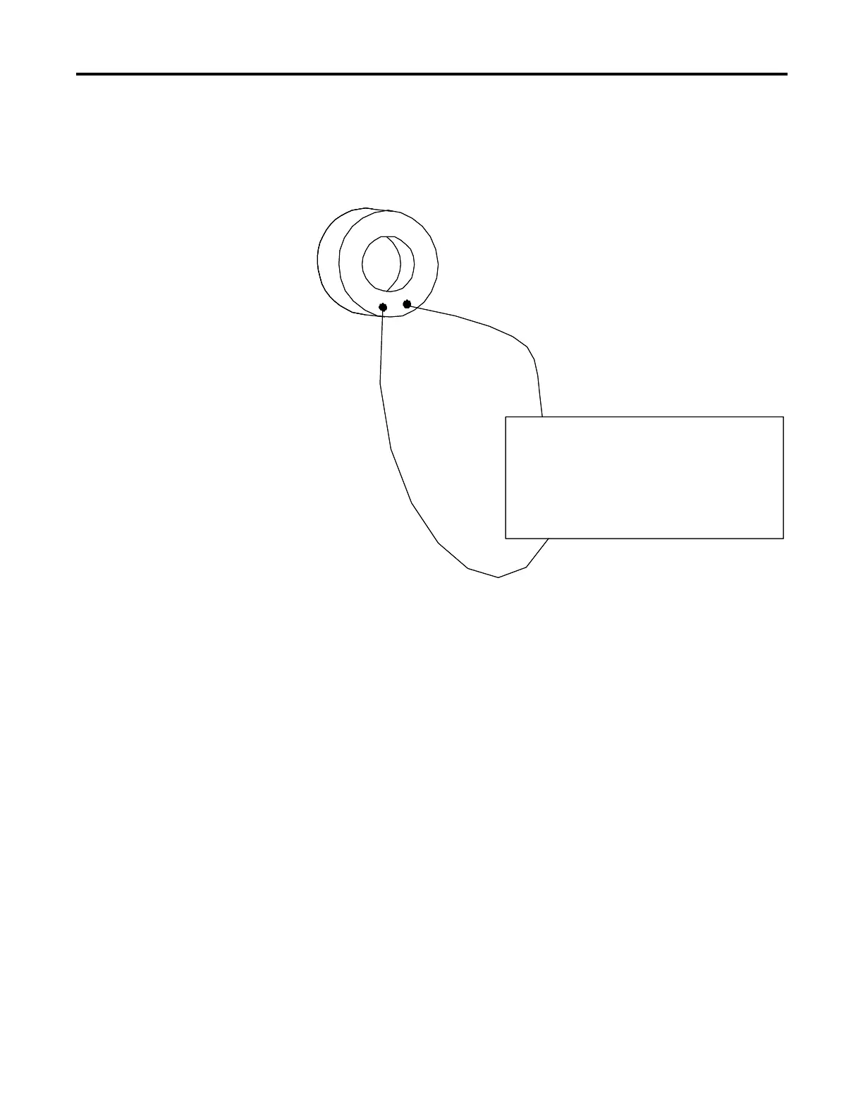
The figure below illustrates the connection of the current transformers to
the converter module.
L1 L3
T1 T3
L2
T2
Converter Module
Current Transformer XY
L1 L3
T1 T3
L2
T2
Converter Module
Current Transformer XY
Figure 2.8 – Current Transformer Connection to Converter Module
X The current transformer (CT) ratio must be programmed in the calibration group for proper current
measurement scaling. See page 5-2 for instructions on programming this parameter.
Y Another current transformer connects L2 and T2, and another connects L3 and T3.
Z The converter module, Cat. No. 825-MCM20, must be used in these applications.
 Loading...


