Troubleshooting 10-19
1560D-UM051D-EN-P – February 2005
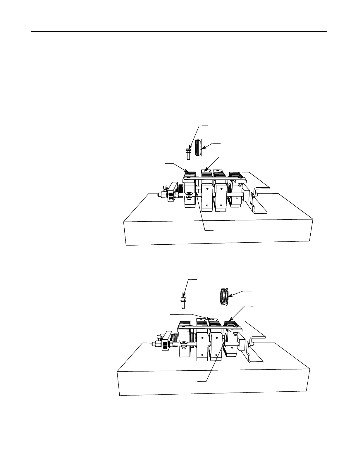
Figure 10.5 – Removal of SCR1
Figure 10.6 – Removal of SCR2
Shorting Bar Hardware
SCR 2
Heatsink 3
Heatsink 2B
Locating Pin
Shorting Bar Hardware
SCR 2
Heatsink 3
Heatsink 2B
Locating Pin
To Remove SCR1:
• Remove shorting bar hardware
• Pry Heatsinks 1 and 2A apart
• Extract SCR
To Insert New SCR:
• Apply thin film of electrical joint compound to
surfaces of SCR
• Install SCR so that it is seated in locating pin of
heatsink (note orientation of SCR).
• Pry heatsinks to close gap, ensuring that SCR is
seated properly in both its locating pins.
• Rotate SCR so that all leads have same direction.
Shorting Bar Hardware
SCR 1
Heatsink 2A
Heatsink 1
Locating Pin
NOTE: The following steps pertain to the 180/360A
power stack assembly with four heatsinks. The
process is similar for a power stack assembly with
only three heatsinks.
To Remove SCR1:
• Remove shorting bar hardware
• Pry Heatsinks 1 and 2A apart
• Extract SCR
To Insert New SCR:
• Apply thin film of electrical joint compound to
surfaces of SCR
• Install SCR so that it is seated in locating pin of
heatsink (note orientation of SCR).
• Pry heatsinks to close gap, ensuring that SCR is
seated properly in both its locating pins.
• Rotate SCR so that all leads have same direction.
Shorting Bar Hardware
SCR 1
Heatsink 2A
Heatsink 1
Locating Pin
Shorting Bar Hardware
SCR 1
Heatsink 2A
Heatsink 1
Locating Pin
NOTE: The following steps pertain to the 180/360A
power stack assembly with four heatsinks. The
process is similar for a power stack assembly with
only three heatsinks.
 Loading...


