Troubleshooting 10-21
1560D-UM051D-EN-P – February 2005
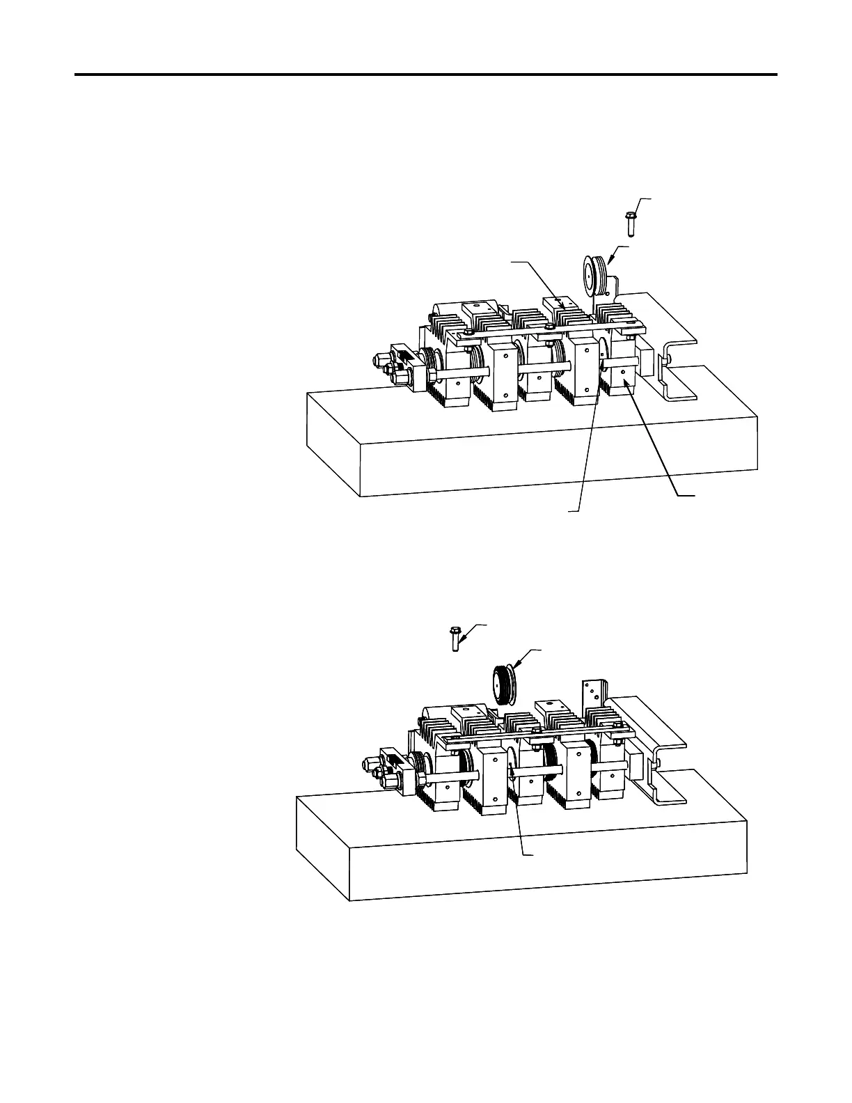
Figure 10.9 – Removal of SCR4
Figure 10.10 – Removal of SCR2
Note: Similar procedure used to remove and replace SCR matched pair 1 and 3.
To Remove SCR4:
• Remove shorting bar hardware
• Pry Heatsinks 4 and 5 apart
• Extract SCR
To Insert New SCR:
• Apply thin film of electrical joint compound to surfaces of SCR
• Install SCR so that it is seated in locating pin of heatsink (note
orientation of SCR).
• Pry heatsinks to close gap, ensuring that SCR is seated properly
in both its locating pins.
• Rotate SCR so that all leads have same direction.
• Proceed to replace SCR’s matched pair (SCR2).
Shorting Bar Hardware
SCR 4
Heatsink 4
Locating Pin
Heatsink 5
Shorting Bar Hardware
SCR 2
Locating Pin
Shorting Bar Hardware
SCR 2
Shorting Bar Hardware
SCR 2
Locating Pin
 Loading...


