3-8 Commissioning Procedures
1560D-UM051D-EN-P – February 2005
Power Supply Tests (cont.) 7. The gate-driver board voltage may be checked by connecting a DC
voltmeter to TP2 (+) and TP1 (-) (See Figure 3.3). With the specified
power supply connected, the voltage should be 12 ± 2 VDC.
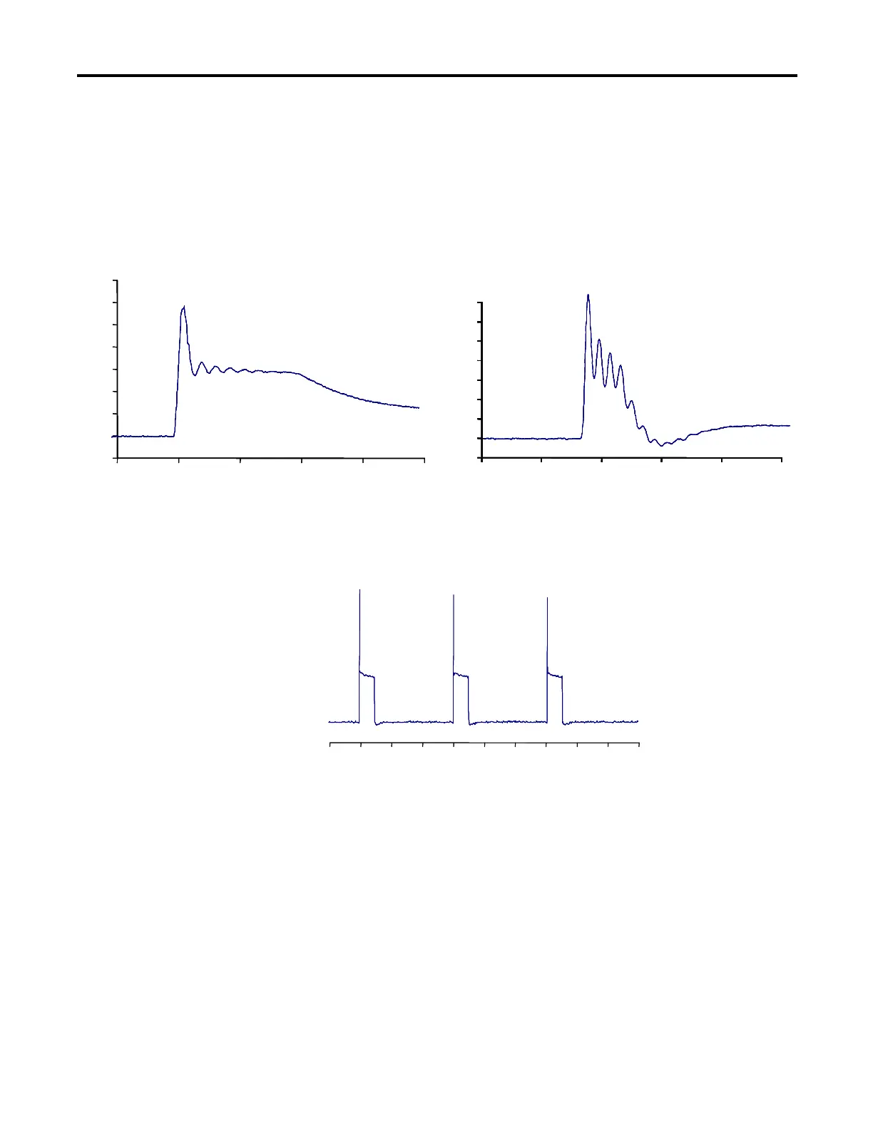
8. The actual gate pulse may be checked by connecting an oscilloscope
between TP7 and TP1 (See Figure 3.3). The pulse should appear as
shown in Figure 3.4a or 3.4b.
Figure 3.4a – Gate Pulse Detail – GEC (GPS) SCR Figure 3.4b – Gate Pulse Detail – ABB SCR
-2.0 -1.5 -1.0 -0.5 0.0 0.5 1.0 1.5 2.0 2.5 3.0
Milliseconds
-2.0 -1.5 -1.0 -0.5 0.0 0.5 1.0 1.5 2.0 2.5 3.0
Milliseconds
Figure 3.5 – Gate Pulse Test Waveform
9. If no pulse is observed, and the yellow LED is lit, check for a shorted
gate on the SCR by removing the green plug and connecting an
ohmmeter to the gate leads. If the LED is not lit, and the circuit
voltage is as specified in step 7 (above), pinch the tab on the fibre-optic
connector and carefully pull it straight out of the receiver. The end of
the connector should glow red to indicate the presence of a gate signal.
If it does not, remove the other end of the cable from the interface
board and check that the grey transmitter is emitting red light. If it is,
the fibre-optic cable must be replaced. If it isn’t, the interface board
should be replaced.
-2
0
2
4
6
8
10
12
14
-202468
Microseconds
Volts
Microseconds
Volts
-2
0
2
4
6
8
10
12
14
-202468
-2
0
2
4
6
8
10
12
14
-202468
Microseconds
Volts
-2
0
2
4
6
8
10
12
14
-202468
-2
0
2
4
6
8
10
12
14
-202468
Microseconds
Volts
Microseconds
Volts
-2
0
2
4
6
8
10
12
14
-202468
Microseconds
Volts
-2
0
2
4
6
8
10
12
14
-202468
-2
0
2
4
6
8
10
12
14
-202468
 Loading...


