Publication 2094-UM001A-EN-P — September 2006
116 Connecting the Kinetix 6000 Drive System
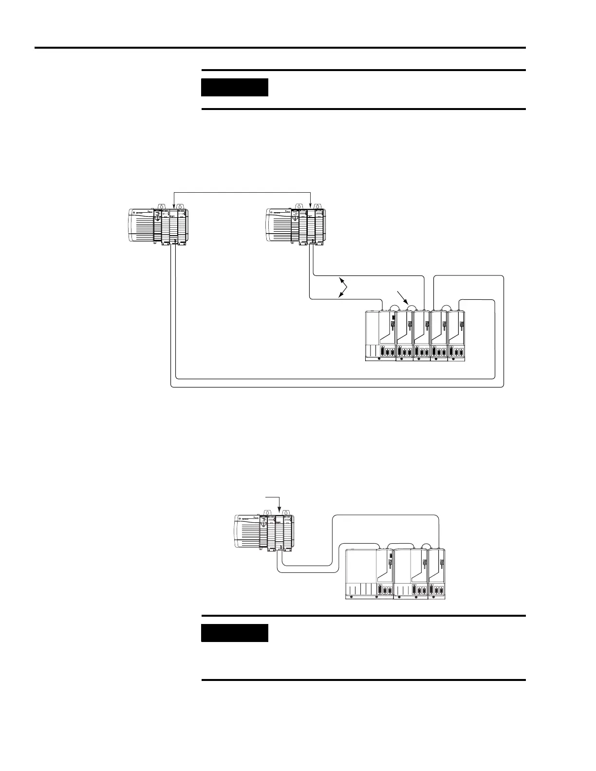
In this example, two Logix modules are installed in separate Logix
chassis.
Fiber-optic Cable Example 2 (two Logix chassis)
When connecting 2094-BM03 and -BM05 (double-wide) axis modules,
use 2090-SCEP0-2, 0.2 m (7.0 in.) cables. When connecting
2094-AMxx, -BMP5, -BM01 and -BM02 (single-wide) axis modules, use
2090-SCEP0-1, 0.1 m (5.1 in.) cables.
Fiber-optic Cable Example 3 (double-wide modules)
IMPORTANT
The CompactLogix platform (1768-M04SE) is limited to four
axes per module.
SERCOS interface
TM
Tx (rear)
Rx (front)
OK
CP
SERCOS interface
TM
Tx (rear)
Rx (front)
OK
CP
Kinetix 6000
System
1756-MxxSE SERCOS interface Modules
Transmit
Receive
Receive
Trans mit
Transmit
SERCOS Fiber-optic Ring
Receive
Trans mit
Receive
SERCOS Fiber-optic Ring
Logix Platform
(ControlLogix is shown)
SERCOS interface
TM
Tx (rear)
Rx (front)
OK
CP
0.1 m
(5.1 in.)
0.2 m
(7.0 in.)
1756-M16SE SERCOS
Interface Module
SERCOS Fiber-optic Ring
Kinetix 6000 System
(5-axis power rail)
Logix Platform
(ControlLogix is shown)
IMPORTANT
Clean the fiber-optic cable connectors prior to installation. Dust
in the connectors can reduce signal strength. For more
information, refer to Fiber-optic Cable Installation and Handling
Instructions, publication 2090-IN010.

 Loading...


