Publication 2094-UM001A-EN-P — September 2006
186 Specifications and Dimensions
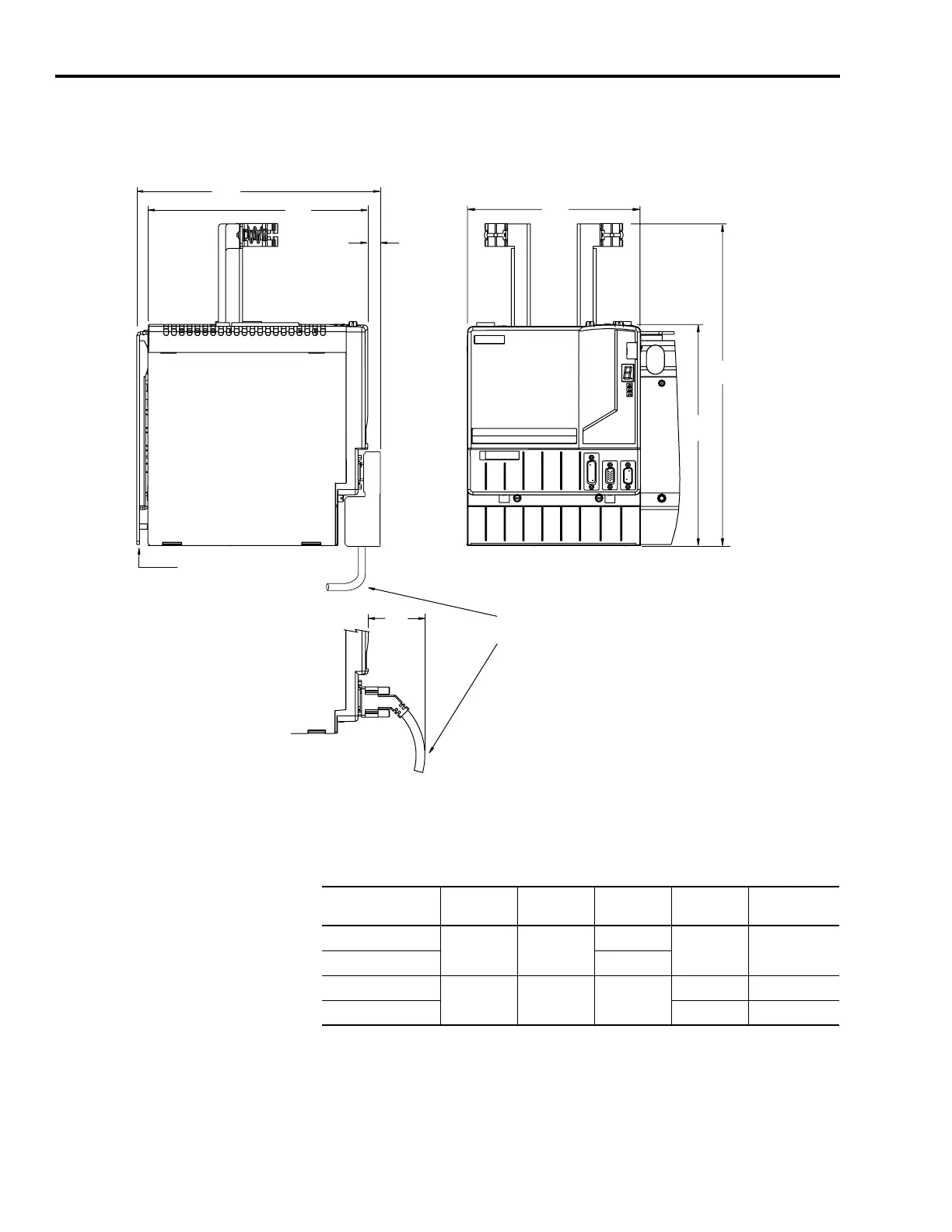
Integrated Axis Module Dimensions
2094-AC16-M03-S and -AC32-M05-S (230V)
2094-BC04-M03-S and -BC07-M05-S (460V)
Modules are shown mounted to the power rail and the dimensions
reflect that in the depth of the module.
IAM Dimensions
8.9
(0.35)
62
(2.45)
A
B
C
E
F
Dimensions are in millimeters (inches)
2090-XXNFxx-Sxx (flying lead) Feedback Cable with
2090-K6CK-D15Mxx Low-profile Connector Kit
2090-UXNFBxx-Sxx (premolded connector) Feedback Cable
Power Rail
Important: Additional clearance below the connector
is necessary to provide the recommended cable-bend
radius.
This view illustrates the
additional clearance required for
premolded cable connectors.
2094-BC04-M03-S (460V) shown
Kinetix 6000 IAM
A
mm (in.)
B
mm (in.)
C
mm (in.)
E
mm (in.)
F
mm (in.)
2094-AC16-M03-S
198 (7.8) 176 (7.0)
125 (4.9)
302 (11.9) 420 (16.5)
2094-AC32-M05-S 196 (7.7)
2094-BC04-M03-S
272 (10.7) 249 (9.8) 196 (7.7)
256 (10.1) 374 (14.7)
2094-BC07-M05-S 318 (12.5) 436 (17.2)

 Loading...


