Publication 2094-UM001A-EN-P — September 2006
202 Interconnect Diagrams
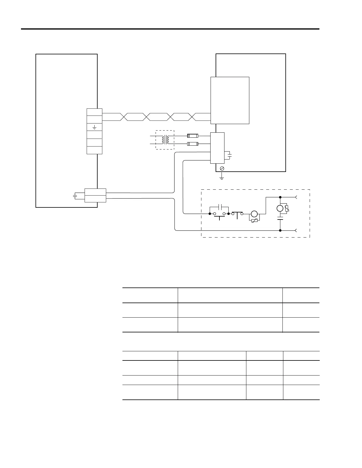
IAM Wiring Example with Single External Active Shunt
Refer to External Shunt Module Specifications on page 184 for a list of
external active shunt module catalog numbers available for the
Kinetix 6000 drives.
1336 Active Shunt Input Fuse Specifications
1336 Active Shunt Fault Relay Specifications
TB1
TB3
1
3
4
2
DC-
DC+
L3
L2
L1
1
2
3
4
5
6
1
2
3
4
5
6
(–) Slave In
(+) Slave In
(+) Master Out
(–) DC Bus
(–) Master Out
(+) DC Bus
CONT EN-
CONT EN+
1
2
Kinetix 6000
Integrated Axis Module
2094-xCxx-Mxx
* Indicates User Supplied Component
Refer to Attention statement (Note 13).
STOP*
START*
CR1*
CR1*
CR1*
M1*
Notes 8, 14
24V ac/dc
or
120V ac
50/60 Hz
DC Bus
Connections
Three-phase
Input (IPD)
Connections
Single-phase Input
115V ac RMS
50/60 Hz
Input Fusing*
Note 23
Contactor Enable
(CED) Connector
Note 14
1336 Master
Fault Relay Note 24
Shunt chassis
ground screw
External Active
Shunt Module (1336-MOD-Kxxxx)
Active Shunt Module Description
Input Current
Requirements
1336-Kx005 or Kx010
Input current requirement to power logic for fault
contact operation.
0.05 A
1336-KB050
Input current requirement to power fan and logic for
fault contact operation.
0.65 A
Parameter Description 120V ac 30V ac
On-state current
Current flow when the contact is
closed
0.6 A 2.0 A
On-state resistance Contact resistance (max) 50 m Ω 50 m Ω
Off-state voltage
Voltage across the contacts
when the relay is open
120V ac 30V ac

 Loading...


