Publication 2094-UM001A-EN-P — September 2006
Interconnect Diagrams 203
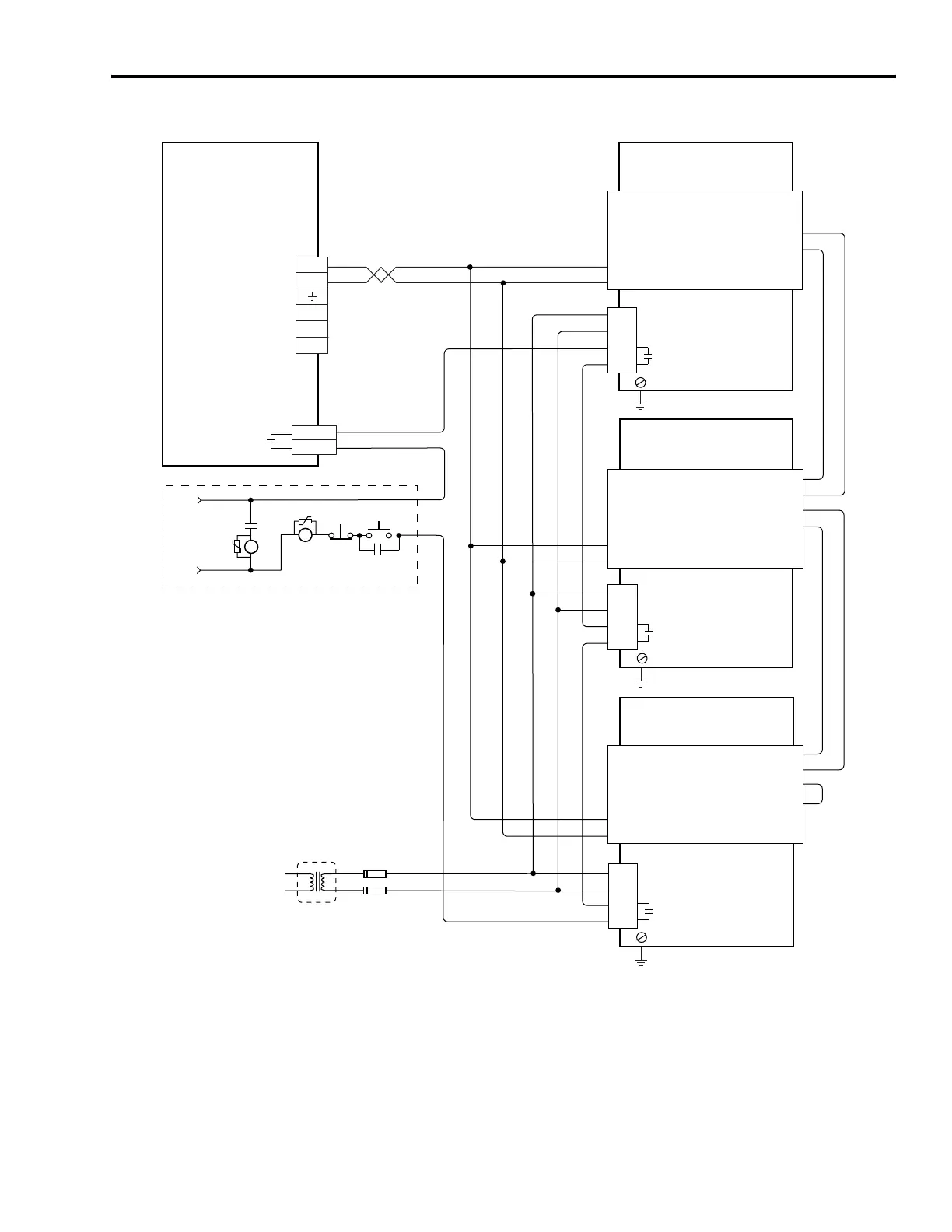
IAM Wiring Example with Multiple External Active Shunts
1
3
4
2
DC-
DC+
L3
L2
L1
1
2
3
4
5
6
5
6
(–) Slave In
(+) Slave In
(+) Master Out
(–) DC Bus
(–) Master Out
(+) DC Bus
CONT EN-
CONT EN+
TB1
TB3
1
3
4
2
TB3
1
3
4
2
TB3
1
2
3
4
(–) Slave In
(+) Slave In
(+) Master Out
(–) DC Bus
(–) Master Out
(+) DC Bus
TB1
(–) Slave In
(+) Slave In
(+) Master Out
(–) DC Bus
(–) Master Out
(+) DC Bus
TB1
5
6
1
2
3
4
1
2
3
4
5
6
1
2
External Active
Shunt Module (1336-MOD-Kxxxx)
Kinetix 6000
Integrated Axis Module
2094-xCxx-Mxx
External Active
Shunt Module (1336-MOD-Kxxxx)
External Active
Shunt Module (1336-MOD-Kxxxx)
* Indicates User Supplied Component
Refer to Attention statement (Note 13).
STOP*
START*
CR1*
CR1*
CR1*
M1*
Notes 8, 14
24V ac/dc
or
120V ac
50/60 Hz
DC Bus
Connections
Three-phase
Input (IPD)
Connections
Single-phase Input
115V ac RMS
50/60 Hz
Contactor Enable
(CED) Connector
Note 14
1336 Master
1336 Slave
1336 Slave
Input Fusing*
Note 23
Fault Relay Note 24
Shunt Chassis
Ground Screw
Fault Relay Note 24
Shunt Chassis
Ground Screw
Fault Relay Note 24
Shunt Chassis
Ground Screw
Note 4
Note 4
Note 4

 Loading...


