Publication 2094-UM001A-EN-P — September 2006
206 Interconnect Diagrams
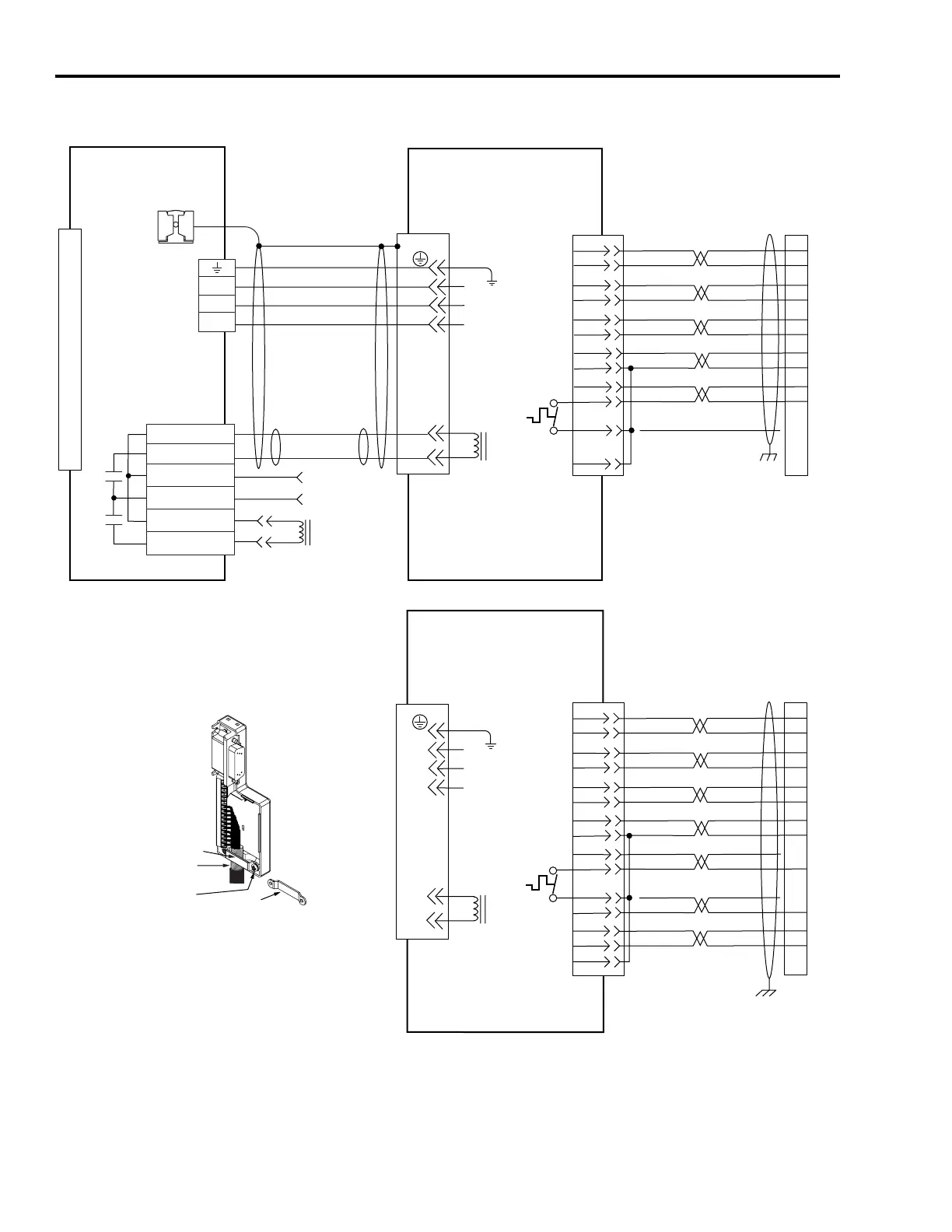
AM Wiring Example with MP-Series (MPL-A/B, MPF-A/B, and MPS-A/B) Motors
D/
C/W
B/V
A/U
BR+
BR-
F/+
G/-
W
V
U
0
1
2
3
4
5
6
7
8
9
10
11
12
13
14
15
SIN+
SIN-
COS+
COS-
DATA+
DATA-
+5VDC
ECOM
GREEN
WHT/GREEN
GRAY
WHT/GRAY
BLACK
WHT/BLACK
RED
WHT/RED
3
4
5
6
1
2
9
10
1
2
3
4
5
10
14
6
14
12
+9VDC
TS+
ORANGE
WHT/ORANGE
11
13
7
11
4
3
2
1
6
5
4
3
2
1
Green/Yellow
Blue
Black
Brown
Black
White
GND
BR+
BR-
F/+
G/-
W
V
U
GND
Shield
W
V
U
MBRK -
MBRK +
COM
PWR
DBRK -
DBRK +
BR+
BR-
D/
C/W
B/V
A/U
TS-
COM
BLUE
AM+
AM-
BM+
BM-
IM+
IM-
+5VDC
ECOM
BLUE
WHT/BLUE
GREEN
WHT/GREEN
GRAY
WHT/GRAY
BLACK
WHT/BLACK
RED
WHT/RED
1
2
3
4
5
10
14
6
12
TS-
S1
–
TS+
ORANGE
WHT/ORANGE
11
S2
S3
COM
YELLOW
WHT/YELLOW
13
8
3
4
5
6
1
2
14
15
16
17
12
11
13
9
10
Motor Brake
Note 22
Resistive Brake
Connections
Motor/Resistive
Brake (BC) Connector
Motor Power
(MP) Connector
Cable Shield
Clamp
Note 10
Kinetix 6000
IAM (inverter) or AM
Note 15
MPL-A/B15xx and -A/B2xx,
MPF-A/Bxxx and MPS-A/Bxxx
Servo Motors with
High Resolution Feedback
Motor Feedback
(MF) Connector
2090-XXNPMF-xxSxx
Motor Power Cable
Note 16
Three-phase
Motor Power
Motor
Feedback
Thermostat
User Supplied
24V dc (1.2A max)
2090-XXNFMF-Sxx
(flying-lead) Feedback Cable
Notes 16, 17, 21
Three-phase
Motor Power
Motor
Feedback
Thermostat
MPL-A/B15xx and -A/B2xx
Servo Motors with
Incremental Feedback
Motor Feedback
(MF) Connector
(IAM/AM)
Motor Feedback
(MF) Connector
(IAM/AM)
2090-XXNFMF-Sxx
(flying-lead) Feedback Cable
Notes 16, 17
Motor Brake
Note 22
Refer to low profile connector
illustration (lower left)
for proper grounding technique.
Refer to low profile connector
illustration (lower left)
for proper grounding technique.
Low Profile Connector
(2090-K6CK-D15M shown)
Grounding Technique for
Feedback Cable Shield
Turn clamp over to hold
small cables secure.
Exposed shield secured
under clamp.
Clamp Screws (2)
Clamp

 Loading...


