Publication 2094-UM001A-EN-P — September 2006
Interconnect Diagrams 207
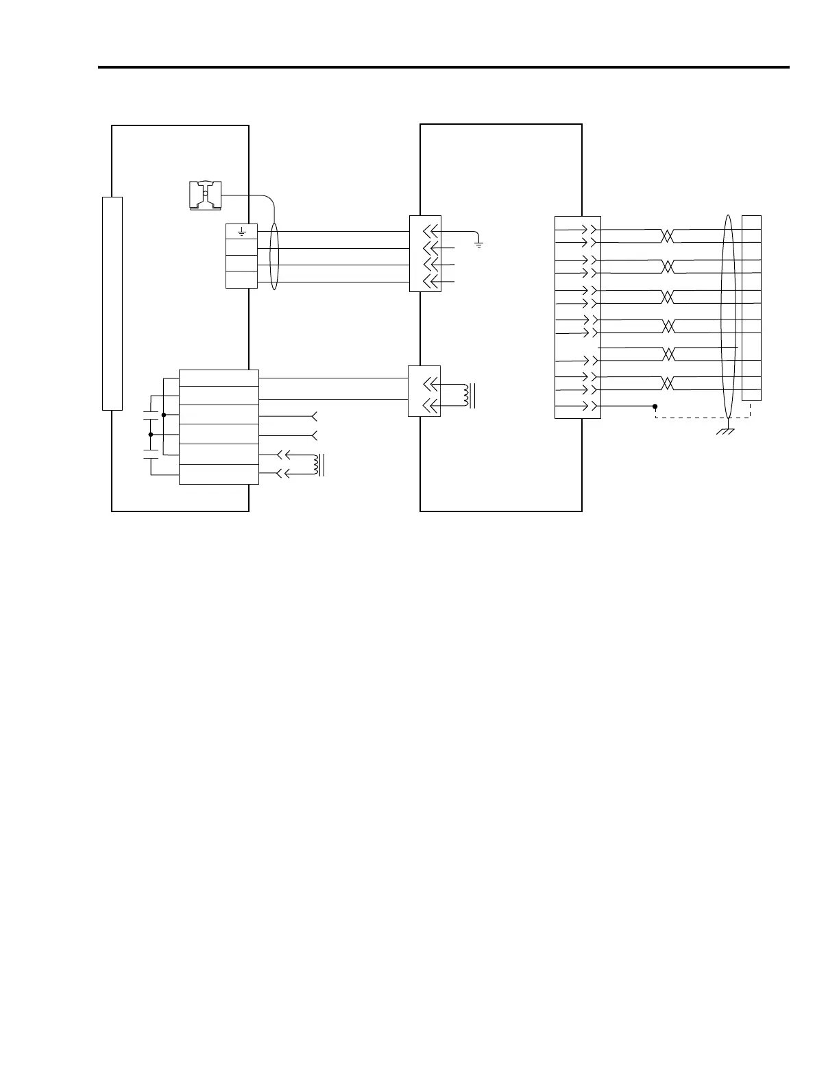
AM (230V) Wiring Example with TL-Series Motors
4
3
2
1
BR+
BR-
1
2
W
V
U
AM+
AM-
BM+
BM-
IM+
IM-
+5VDC
ECOM
BLUE
WHT/BLUE
GREEN
WHT/GREEN
GRAY
WHT/GRAY
BLACK
WHT/BLACK
RED
WHT/RED
7
8
1
2
3
4
5
10
14
6
12
6
S1
9
S2
S3
YELLOW
WHT/YELLOW
11
15
13
8
GND
1
2
3
4
5
10
0
1
2
3
4
5
6
7
8
9
10
11
12
13
14
15
4
3
2
1
6
5
4
3
2
1
Green/Yellow
Blue
Black
Brown
Black
White
W
V
U
MBRK -
MBRK +
COM
PWR
DBRK -
DBRK +
BR+
BR-
GREEN
SHIELD
Motor Brake
Three-phase
Motor Power
Motor Feedback
TL-Series (230V) Servo Motors
with Incremental Feedback
Motor Feedback
(MF) Connector
(IAM/AM)
2090-XXNFT-Sxx Feedback Cable
with pre-molded connector
Note 16
Resistive Brake
Connections
Motor/Resistive
Brake (BC) Connector
Motor Power
(MP) Connector
Cable Shield
Clamp
Note 10
Kinetix 6000
IAM (inverter) or AM
Note 15
Motor Feedback
(MF) Connector
2090-XXNPT-16Sxx
Motor Power Cable
Note 16
User Supplied
24V dc (1.2A max)
2090-DANBT-18Sxx
Motor Brake Cable
Note 16

 Loading...


