Publication 2094-UM001A-EN-P — September 2006
Interconnect Diagrams 213
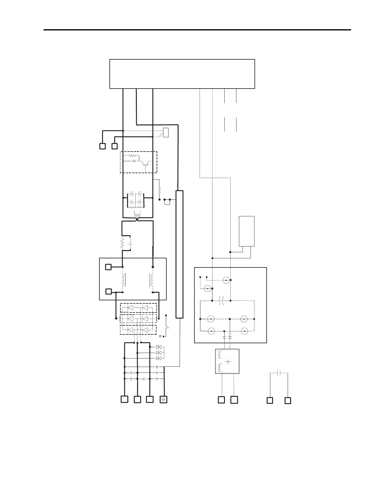
IAM (converter) Block Diagram
L1
L2
L3
L1
L2
120K
CONT_EN2
CONT_EN1
GSHUNT
SYS_OK
DC+
DC-
CHASSIS
CTRL2
CTRL1
DC+
DC-
CTRL-
CTRL+
DC+
DC-
Vsns
DCL1
DCL2
Vcc
CONV_OT
95C
Shunt Circuit
(2)
Common Bus
Power Connections
POWER
RAIL
Control Power
Loss Detector
Rectifier Circuit
(2)
EMC Filter
(1)
DC Link
Inductor
(3)
Ground Jumper
(4)
Gnd Flt CT
Chassis
Three-phase
ac Input
Control Power
ac Input
DROK/
CONT_EN
(1)
EMC filter present only on 460V converters.
(2)
Rectifier and shunt circuits present only on 230V converters.
(3)
Internal dc link inductor present on 460V converters. Connectors for external dc
link inductor present on 230V converters.
(4)
Ground jumper shown in default configuration (grounded facility power).

 Loading...


