Publication 2094-UM001A-EN-P — September 2006
214 Interconnect Diagrams
Kinetix 6000 drives with the safe-off feature ships with the wiring
header and motion allowed jumper installed. In this configuration, as
illustrated below, the safe-off feature is not used.
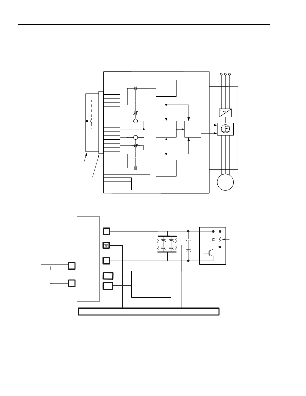
Safe-off Feature Block Diagram
Shunt Module Block Diagram
K1
K2
K1-A
K2-A
K2-C
K1-C
+24V
M
Safe-Off Option
6
5
7
3
4
1
2
8
9
Wiring Header
Motion Allowed Jumper
Gate Control
Power Supply
Safety Monitor
uC
Gate Control
Enable Signal
+24V_COM
FDBK1+
FDBK1-
ENABLE-
ENABLE1+
ENABLE2+
FDBK2+
FDBK2-
Gate Control
Circuit (CCP)
+24V
Safe-Off (SO)
9-pin Connector
DRIVE ENABLE
+24V_COM
POWER
RAIL
DC+
DC-
CTRL 2
SYSOK
GSHUNT (2)
SMPS
CTRL 1
Shunt Circuit
Internal
or External
Shunt
Resistor
+5V (Control)
+/-15V (IGBT)
24V (Control)
Chassis

 Loading...


