EasyManuals Logo

Rockwell Automation Allen-Bradley Kinetix 6000 User Manual

Rockwell Automation Allen-Bradley Kinetix 6000
268 pages
To Next Page IconTo Next Page
To Previous Page IconTo Previous Page
Page #46 background imageLoading...
Page #46 background image
Publication 2094-UM001A-EN-P — September 2006
46 Mounting the Kinetix 6000 Drive System
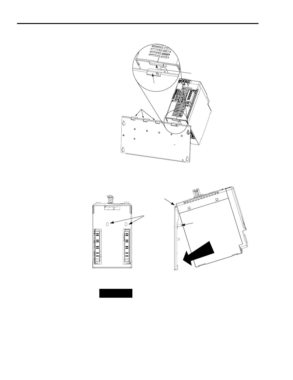
4. Hang the mounting bracket from the slot on the power rail.
5. Pivot module downward and align the guide pins on the power
rail with the guide pin holes in the back of the module.
Slots for additional axis modules,
shunt module, or slot filler.
Power Rail Slot
Mounting Bracket
Power Rail
Integrated Axis Module
Guide Pin
Holes
Power rail
(side view)
in upright
vertical position.
Integrated Axis Module
(side view)
Integrated Axis Module
(rear view)
Guide Pins
Pivot module downward
and align with guide pins.
TIP
The IAM can have two or three power rail connectors and guide
pins, the AM can have one or two, all other modules have one.

Table of Contents

Other manuals for Rockwell Automation Allen-Bradley Kinetix 6000

Questions and Answers:

Question and Answer IconNeed help?

Do you have a question about the Rockwell Automation Allen-Bradley Kinetix 6000 and is the answer not in the manual?

Rockwell Automation Allen-Bradley Kinetix 6000 Specifications

General IconGeneral
BrandRockwell Automation
ModelAllen-Bradley Kinetix 6000
CategoryServo Drives
LanguageEnglish

Related product manuals