Publication 2094-UM001A-EN-P — September 2006
Mounting the Kinetix 6000 Drive System 47
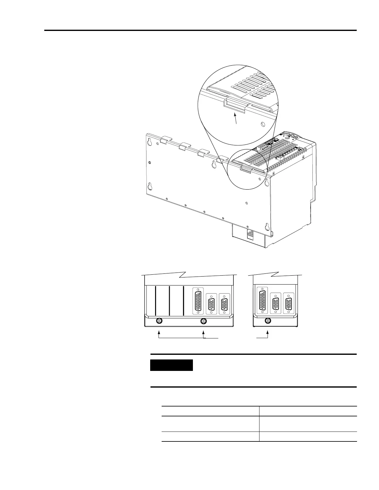
6. Gently push the module against the power rail connectors and
into the final mounting position.
7. Use 2.26 Nm (20 lb-in.) torque to tighten the mounting screws.
8. Determine if you have additional modules to mount
.
Power Rail
Integrated Axis Module
Bracket secured in slot.
Bottom front view of
single-wide AM, SM, or PRF
(AM is shown).
Mounting Screws
Bottom front view of
double-wide IAM or AM
(AM is shown).
IMPORTANT
There are two mounting screws when mounting
2094-AC32-M05, -BC04-M03, and -BC07-M05 (double-wide)
IAMs and 2094-AM05, -BM03, and -BM05 (double-wide) AMs.
If You Then
Have additional modules to mount
Return to Step 1 and complete installation of
your next AM, SM, or PRF module.
Do not have additional modules to mount Go to Mounting the External Shunt Module.

 Loading...


