Rockwell Automation Publication 2099-UM001G-EN-P - December 2022 109
Configure and Start the Kinetix 7000 Drive System Chapter 5
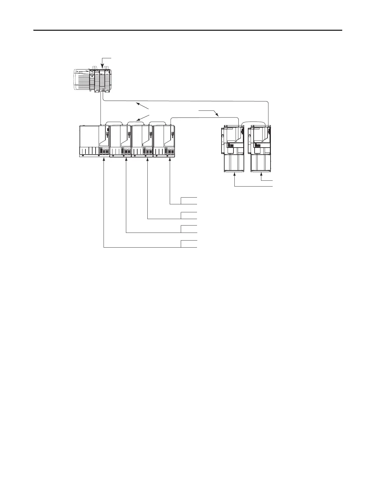
Figure 67 - Node Addressing Example 2
In this example, a Kinetix 6000 (8-axis) power rail contains a double-wide IAM,
and three double-wide AMs.
The leftmost slot of a double-wide module determines the node address. So, in
the example above, node addresses 02, 04, and 06 (the rightmost slots of the
double-wide modules) are not used.
The Kinetix 7000 (2-axis) drive system contains two drives. The base node
address of the system must be set for an address of 9.
SERCO S interface
TM
Tx (rear)
Rx (front)
OK
CP
08 = Not Used (AM rightmost slot)
07 = AM (axis 4) Node Address
06 = Not Used (AM rightmost slot)
05 = AM (axis 3) Node Address
04 = Not Used (AM rightmost slot)
03 = AM (axis 2) Node Address
02 = Not Used (IAM rightmost slot)
01 = IAM (axis 1) Base Node Address
Sercos Fiber-optic Ring
1756-MxxSE Sercos
interface Module
Kinetix 6000
(8-axis power rail)
Trans mit
Receive
Logix Chassis/PCI Card
(ControlLogix chassis is shown)
Kinetix 7000
(2-axis)
10 = Drive (axis 2) Node Address
09 = Drive (axis 1) Node Address

 Loading...


