Rockwell Automation Publication 2099-UM001G-EN-P - December 2022 77
Connect the Kinetix 7000 Drive System Chapter 4
Set the Ground Jumper in
Select Power Configurations
Setting the ground jumper is necessary when using an ungrounded, corner-
grounded, and impedance-grounded power configuration. Also, set the ground
jumper when you are using the 8720MC regenerative power supply, or any active
converter, for DC-bus voltage. Setting the ground jumper involves accessing the
power chassis and removing jumper plugs or disconnecting wires on the power
terminals.
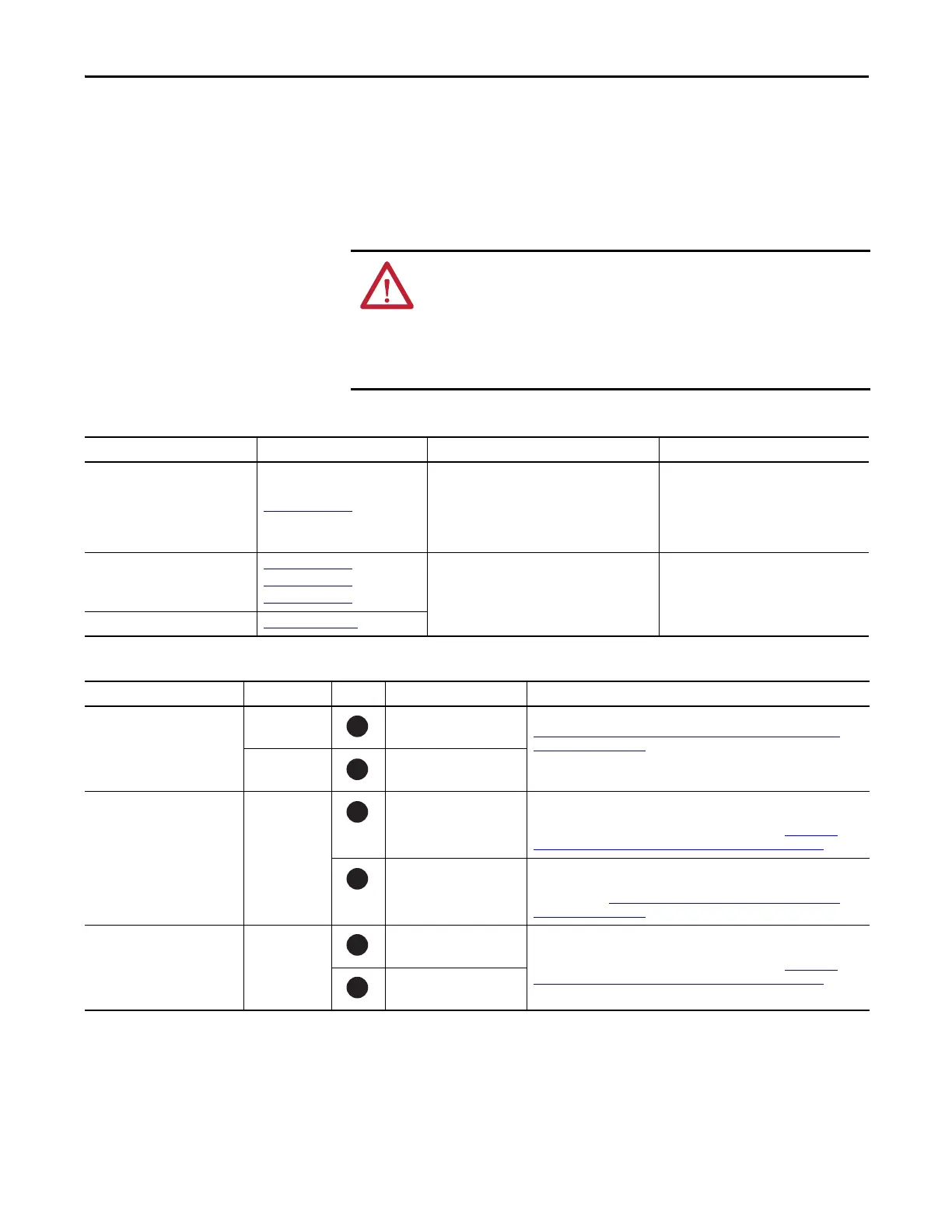
Table 32 - Ground Jumper Configurations
Table 33 - Jumper/Wire Location and Removal Instructions
ATTENTION: To avoid personal injury, the ground jumper access area must be
kept closed when power is applied. If power was present and then removed,
wait at least 5 minutes for the DC-bus voltage to dissipate and verify that no DC-
bus voltage exists before accessing the ground jumper.
Because the unit no longer maintains line-to-neutral voltage protection, risk of
equipment damage exists when you remove the ground jumper.
Ground Configuration Example Diagram Ground Jumper Configuration Benefits of Correct Configuration
Grounded (wye) Figure 44 on page 73
Installed (default setting)
• UL and EMC compliance
• Reduced electrical noise
• Most stable operation
• Reduced voltage stress on components and
motor bearings
• Corner grounded
• Impedance grounded
• AC-fed ungrounded
Figure 45 on page 74
Figure 46 on page 75
Figure 47 on page 76
Removed
• Helps avoid severe equipment damage
when ground faults occurs
• Reduced leakage current
DC-bus from active converter Figure 75 on page 165
Drive Jumper/Wire ID No. Component Location
2099-BM06-S, 2099-BM07-S and
2099-BM08-S
PEA Common mode capacitor Remove the two jumpers located above the power terminal block. See
Remove the Ground Jumper on 2099-BM06-S, 2099-BM07-S, and 2099-
BM08-S Drives on page 78.
PEB MOVs
2099-BM09-S and
2099-BM10-S
Green/yellow
wire
Common mode capacitor Remove DC-DC converter and drive top cover, and disconnect the green/
yellow wire from the drive chassis. Insulate and secure the wire to prevent
unintentional contact with the chassis or components. See Remove the
Ground Wires on 2099-BM09-S and 2099-BM10-S Drives on page 79.
MOVs/input filter cap Disconnect the green/yellow wire next to the power terminal block. Insulate
and secure the wire to prevent unintentional contact with the chassis or
components. See Remove the Ground Wires on 2099-BM09-S and 2099-
BM10-S Drives on page 79.
2099-BM11-S and
2099-BM12-S
Green/yellow
wire
Common mode capacitor Disconnect the two green/yellow wires from the PE terminals on the power
terminal block. Insulate and secure each of these wires to prevent
unintentional contact with the chassis or components. See Remove the
Ground Wires on 2099-BM11-S and 2099-BM12-S Drives on page 79.
MOVs
1
2
3
4
5
6

 Loading...


