Rockwell Automation Publication 2099-UM001G-EN-P - December 2022 33
Install the Kinetix 7000 Drive System Chapter 2
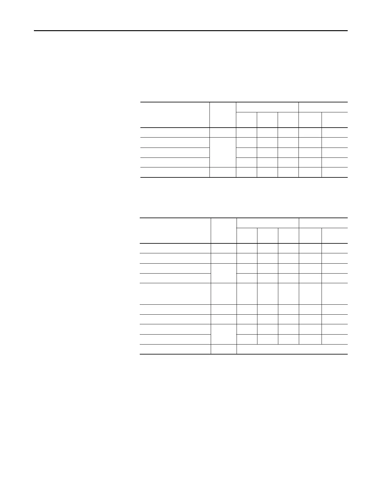
Cable Categories for Kinetix 7000 Systems
The table below indicates the zoning requirements of input power cables
connecting to the Kinetix 7000 drive.
Table 4 - Kinetix 7000 Drive
The table below indicates the zoning requirements of power and control cables
connecting to the Kinetix 7000 system.
Table 5 - Kinetix 7000 System
Wire/Cable Connector Zone Method
Very
Dirty
Dirty Clean Ferrite
Sleeve
Shielded
Cable
Control Power CP X
DC-/DC+
PTB
X
L1, L2, L3 (shielded cable) X X
L1, L2, L3 (unshielded cable) X
DPI™ DPI X X
Wire/Cable Connector Zone Method
Very
Dirty
Dirty Clean Ferrite
Sleeve
Shielded
Cable
U, V, W (Motor Power) MP X X
GPR+, GPR- (Motor Brake) GPR X
24V DC (PWR), COM, filtered
GPIO, GPR
X
24V DC (PWR), COM, unfiltered X
24V DC (PWR), COM, safety enable,
and feedback signals for Safe Torque
Off feature
SO X
Motor Feedback MF X X
Auxiliary Feedback AF X X
Registration and Analog Outputs
IOD
XX
Others X
Fiber-optic Rx and Tx No Restrictions

 Loading...


