96 Rockwell Automation Publication 2099-UM001G-EN-P - December 2022
Chapter 4 Connect the Kinetix 7000 Drive System
Wire Panel-mounted Breakout Board Kits
The panel-mounted breakout board kit (catalog number 2090-UXBK-D15xx)
includes a (DIN rail) terminal block and cable. The cable connects between the
terminal block and the motor feedback (MF) connector. Wires from your flying-
lead motor feedback cable connect to the terminals.
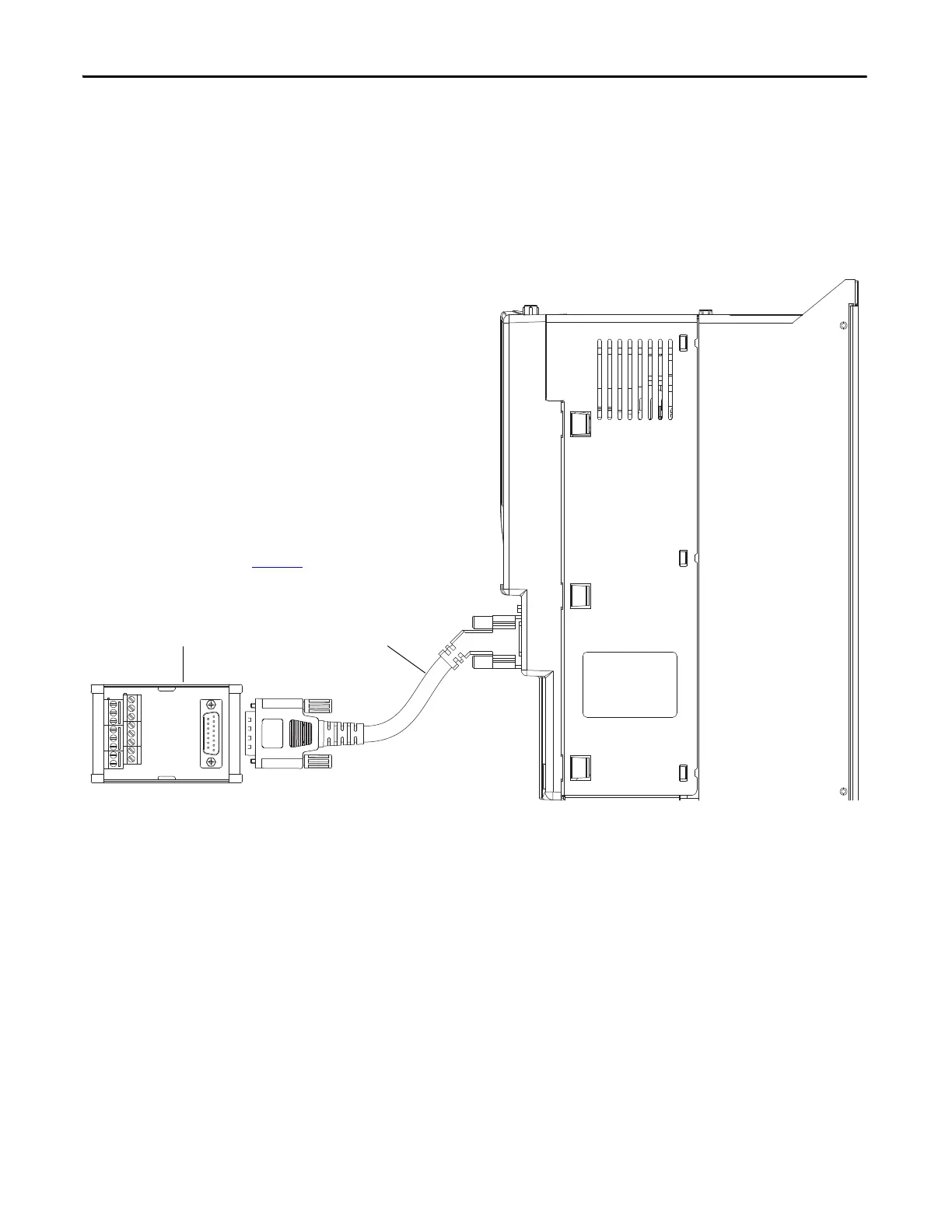
Figure 56 - Panel-mounted Breakout Board Connection Example
2090-UXBC-D15xx
Breakout Cable
See the Motor Feedback Breakout Board
Installation Instructions, publication 2090-IN006,
for Connector Breakout Board Specifications.
Kinetix 7000 Drive
(Side View)
2090-UXBB-D15
Panel-mounted Breakout Board

 Loading...


