Rockwell Automation Publication 2099-UM001G-EN-P - December 2022 79
Connect the Kinetix 7000 Drive System Chapter 4
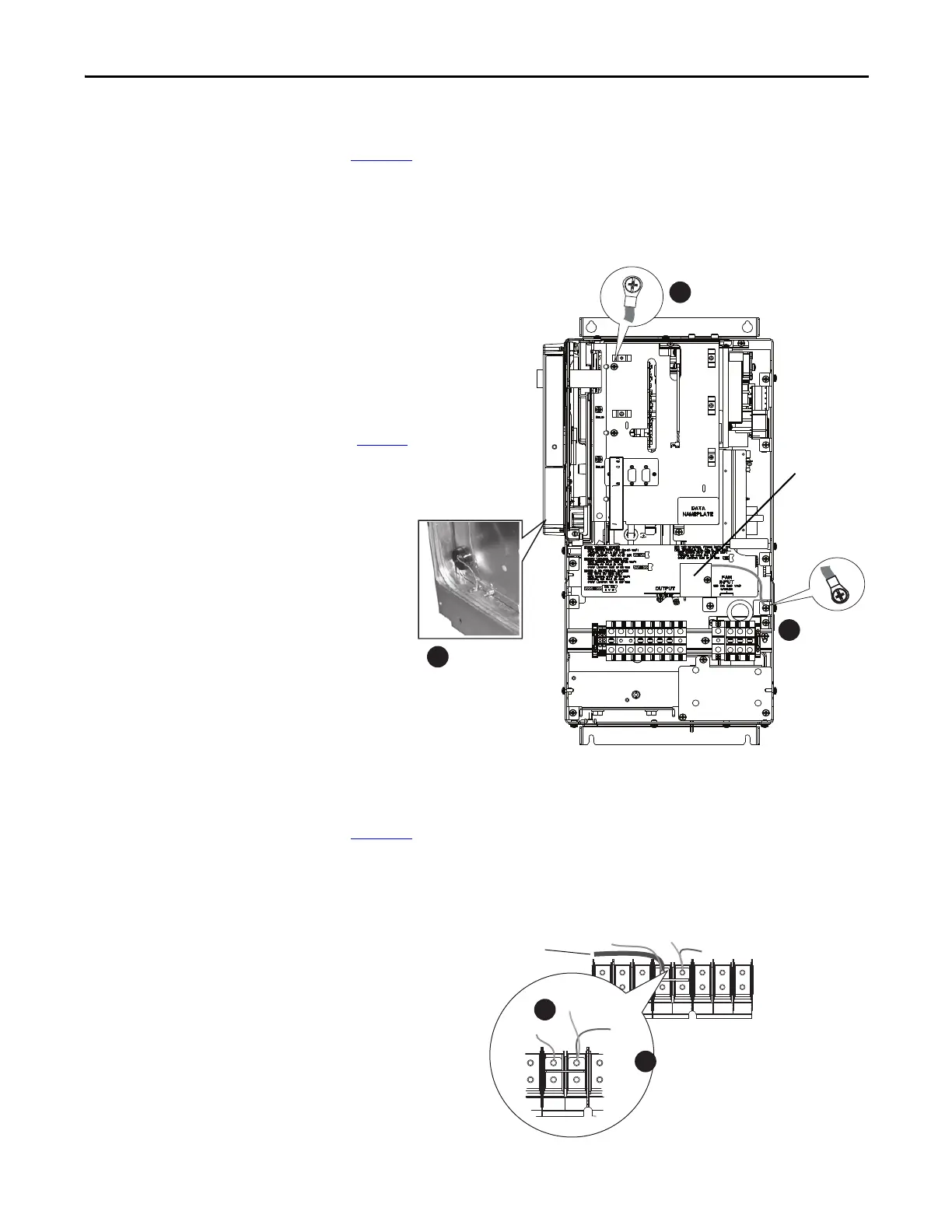
Remove the Ground Wires on 2099-BM09-S and 2099-BM10-S Drives
Figure 49 shows the locations of the common mode capacitor and MOV/input
filter capacitor ground wires in 2099-BM09-S and 2099-BM10-S drives. The
common mode capacitor ground wire is indicated by callout 3 and the MOV/
input filter cap ground wire is indicated by callout 4.
Figure 49 - Ground Wire Locations on Terminal Block of 2099-BM09-S and 2099-BM10-S
Remove the Ground Wires on 2099-BM11-S and 2099-BM12-S Drives
Figure 50 shows the locations of the common mode capacitor and MOV ground
wires in 2099-BM11-S and 2099-BM12-S drives. The common mode capacitor
ground wire is indicated by callout 5 and the MOV ground wire is indicated by
callout 6.
Figure 50 - Ground Wire Location on Power Terminal Block of 2099-BM11-S and 2099-BM12-S
Note: You must remove the DC-DC
converter and drive top cover to access
and remove the common mode
capacitor ground wire. See the Kinetix
7000 DC-DCConverter and ControlBoard
Kits Installation instructions, publication
2099-IN002
, for instructions.
4
U
T1
V
T2
W
T3
R
L1
S
L2
INPUTOUTPUT
T
L3
PE PE
PE PE
MOV
CM Cap

 Loading...


