Rockwell Automation Publication 2099-UM001G-EN-P - December 2022 11
Start Chapter 1
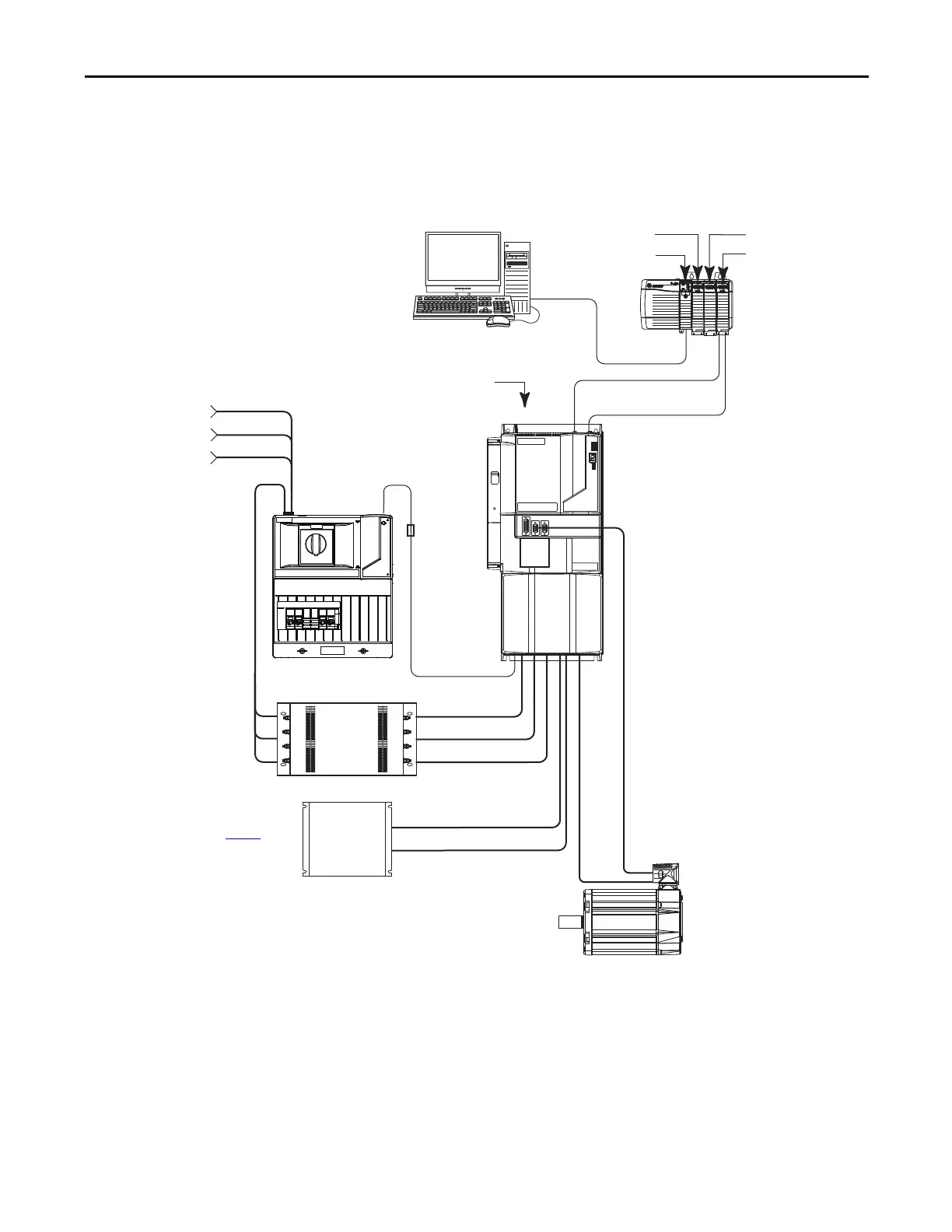
Typical Drive System
Diagrams
Typical Kinetix 7000 system installations include three-phase AC configurations,
with and without the line interface module (LIM), and DC common bus
configurations.
Figure 1 - Kinetix 7000 System Configuration with LIM and External Resistive Shunt
24V DC
Control Power
External Shunt Module (optional component). See
External Shunt Modules on page 157
for more
information.
2090-XXLF-TCxxxx
AC Line Filter
2094-BL75S
Line Interface Module
(optional component)
460V AC
Three-Phase
Input Power
RSLogix 5000 Software
Input
Logix 5000® Controller
Output
1756-MxxSE Sercos
Interface Module
2090-SCxxx-x
Sercos Fiber-optic Ring
Commissioning
2099-BMxx-S Kinetix 7000 Drive
Kinetix HPK, MMA, MPL, MPM,
and RDB Servo Motors
ControlLogix Chassis
Motor Power Cable
Encoder
Feedback
Cable
2090-K6CK-Dxxx
Low Profile Connector Kits for
I/O, Motor Feedback,
and Auxiliary Feedback
Safe Torque Off,
General Purpose I/O,
General Purpose Relay
Connections

 Loading...


