Rockwell Automation Publication 2099-UM001G-EN-P - December 2022 131
Configure and Start the Kinetix 7000 Drive System Chapter 5
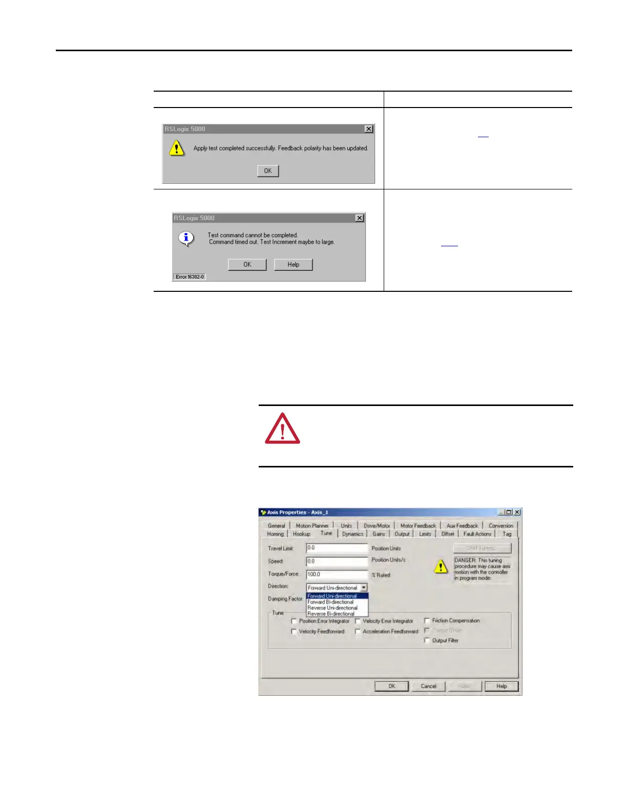
9. Determine if your test completed successfully.
Tune the Axes
Follow these steps to tune the axes.
1. Verify the load is still removed from the axis being tuned.
2. Click the Tune tab.
If Then
Your test completes successfully, this dialog box opens. 1. Click OK.
2. Remove Hardware Enable Input signal (IOD-2).
3. Go to Tune the Axes on page 131
.
Your test failed, this dialog box opens. 1. Click OK.
2. Verify the Bus Status LED turned solid green during the test.
3. Verify that the Hardware Enable Input signal (IOD-2) is
applied to the axis you are testing.
4. Verify conversion constant entered in the Conversion tab.
5. Return to main step 6 and run the test again.
ATTENTION: To reduce the possibility of unpredictable motor response,
tune your motor with the load removed first, then reconnect the load
and perform the tuning procedure again to provide an accurate
operational response.

 Loading...


