Rockwell Automation Publication 2099-UM001G-EN-P - December 2022 25
Install the Kinetix 7000 Drive System Chapter 2
Minimum Clearance Requirements
This section provides information to assist you in sizing your cabinet and
positioning your Kinetix 7000 system components.
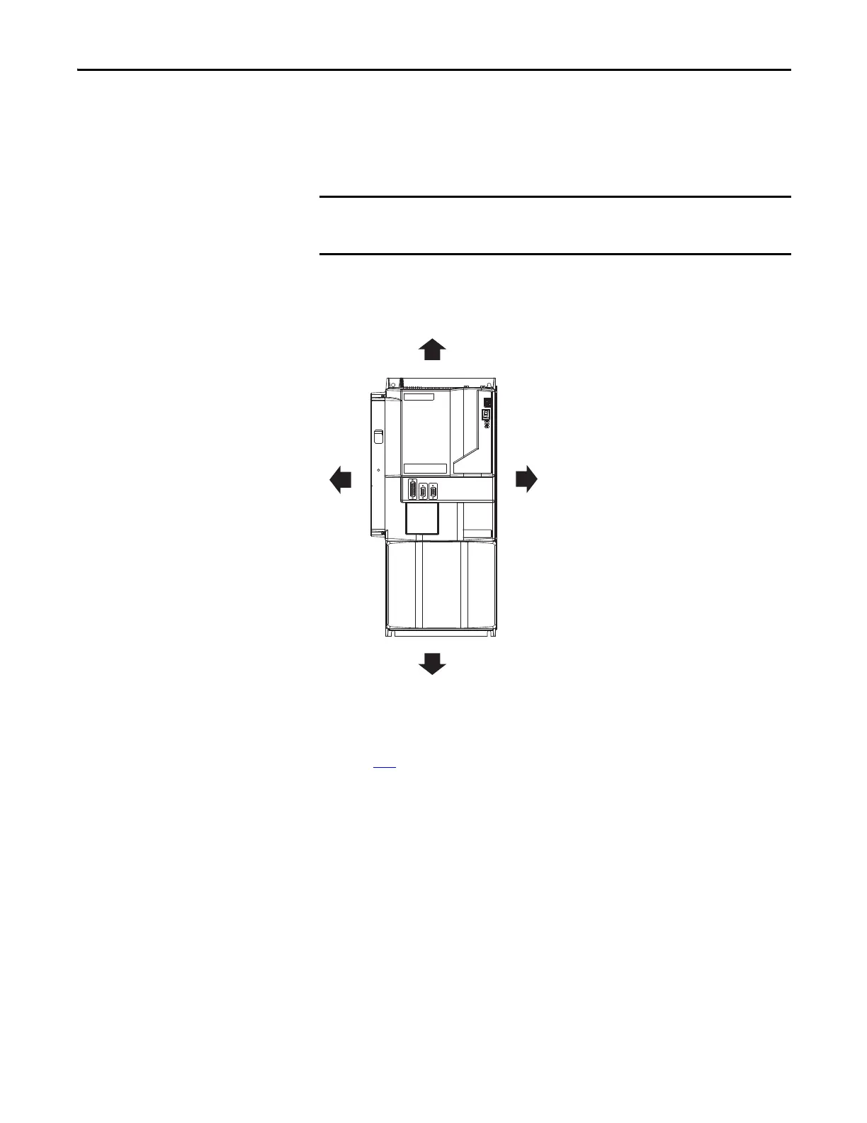
Figure 7 - Minimum Clearance Requirements
See page 152 for power dissipation specifications.
Mount the module in an upright position as shown. Do not mount the
module on its side.
50.8 mm (2.0 in.) clearance right
of module is required
Minimum cabinet depth = 300 mm (11.8 in.)
Cable bend radius requires a minimum of
60 mm (2.4 in.) from the front panel connections.
101.6 mm (4.0 in.) clearance for
airflow and installation
50.8 mm (2.0 in.) clearance left
of module is required
101.6 mm (4.0 in.) clearance for
airflow and installation

 Loading...


