172 Rockwell Automation Publication 2099-UM001G-EN-P - December 2022
Appendix B Interconnect Diagrams
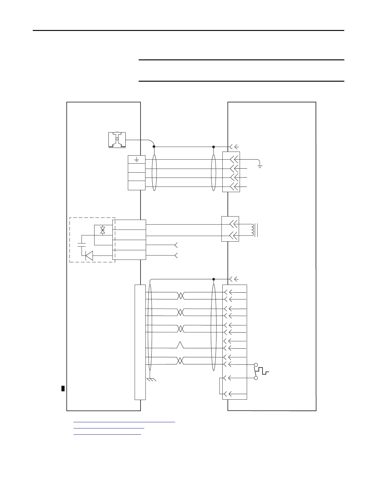
Kinetix 7000 Drive/Rotary Motor Wiring Examples
Figure 82 - Kinetix MPL Motors (Bayonet Style Connector)
The Kinetix MPL motor wiring example on this page applies to motors
equipped with bayonet connectors.
D
C
B
A
W
V
U
4
3
2
1
Green/Yellow
1/Blue
2/Black
3/Brown
GND
W
V
U
BR+
BR-
A
C
3
2
4
1
Black
White
GPR1-
GPR1+
COM
24VDC
SIN+
SIN-
COS+
COS-
DATA+
DATA-
GREEN
WHT/GREEN
BLACK
WHT/BLACK
RED
WHT/RED
+9VDC
TS+
ORANGE
WHT/ORANGE
C
D
E
F
A
B
K
L
S
P
N
R
1
2
3
4
5
10
14
6
7
11
Dashed lines denote
an internal circuit
K
ECOM
WHT/GRAY
Motor Brake
(2)
General Purpose Relay
(GPR) Connector
Motor Power
(MP) Connector
Cable Shield
Clamp
Cable shield clamp must be used to
meet CE and UK requirements. No
external connection to ground
required.
(3)
Kinetix MPx 400V-class Servo Motors
with Absolute Encoder
Motor Feedback
(MF) Connector
(3)
Motor Power (Three-phase)
(2)
Motor Feedback
(2)
Thermostat
Kinetix 7000 Drive
Customer-supplied
24V DC (2A max)
(1)
2090-XXxPMP-xxSxx
Motor Power Cable
2090-UXxBMP-18Sxx
Brake Cable
2090-XXxFMP-Sxx
Flying-lead Feedback Cable
Motor Connector Shell
Motor Connector Shell
(1) See Customer-supplied 24V DC Power Supply Notes
on page 173 for important wiring information.
(2) See Kinetix MPL
Motor Connectors on page 82 for more information on bayonet and circular DIN connectors.
(3) See Wire Low-profile Connectors
on page 97 for more information on grounding feedback cables when using low-profile connectors.
2090-K6CK-D15M connector
kit

 Loading...


