Installation
Electrical Connections
104 MagneMotion
Rockwell Automation Publication MMI-UM013B-EN-P - April 2020
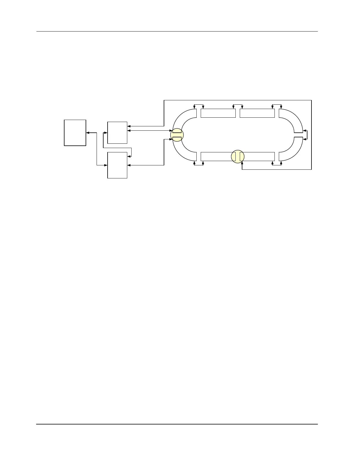
RS-422 and Ethernet Motor Connections
This method mixes the traditional RS-422 connection scheme for connecting the motors to
other motors and to the node controllers and the new Ethernet connection scheme as shown in
Figure 5-12. This method is only used with NC-S, NC-12, and NC LITE node controllers
when combining RS-422 motors and Ethernet motors in the same transport system. See the
MagneMover LITE User Manual for detailed connection information.
Figure 5-12: RS-422 and Ethernet Motor Wiring Example
1. Connect the motors that use RS-422 communications as described in RS-422 Only
Motor Connections.
2. Connect a Cat5 Ethernet cable from the switch where the node controller is connected
to the first motor in the Ethernet chain.
3. Connect a Cat5 Ethernet cable from the downstream connection on the motor to the
upstream connection on the next motor in the chain.
4. Continue making motor-to-motor Ethernet connections until the last motor in the path
is reached.
5. Create a MICS file to define the Ethernet motor connections.
P2M1
x.y.2.1
P2M2
x.y.2.2
HLC &
Node
Controller
Host
Controller
Relay
RS-422 Motor RS-422 Motor
P1M1
P1M2 P1M3
P1M4
P1M5
P1M6
RS-422
Motor
Enet
Motor
RS-422
Motor
RS-422
Motor
Relay
Enet
Switch
Enet Motor RS-422 Motor
Loop Transport System:
Mixed En et and RS-422 motors, Two Paths
One Enet Chain, One RS-422 Chain

 Loading...


