Specifications and Site Requirements
Electrical Specifications
Node Controller Hardware User Manual 65
Rockwell Automation Publication MMI-UM013B-EN-P - April 2020
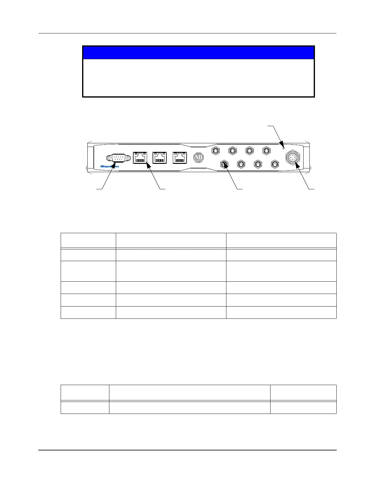
Figure 4-11: NC-S Node Controller Electrical Connections, Controls, and Indicators
NOTICE
Connecting to the DC power connector on the NC-S node controller must be
done with the power supply off. Connecting with the power supply on can
cause a short circuit at the connector, which can damage the power supply or
any other equipment being powered by that power supply.
Table 4-1: NC-S Node Controller Electrical Connections
Label Description Connector Type
CONSOLE External terminal DE-9, Male
NET0 Ethernet - 10/100/1000 Base-Tx
(auto-MDIX, auto-negotiation)
RJ45, Female
NET1, NET2 not used RJ45, Female
1-8 RS-422 motor communications M8 Nano-Mizer, 4-Pin, Male
*
* MagneMotion recommends that the odd number connectors be used for upstream connections and the even
number connectors be used for downstream connections.
POWER 24-48V DC ±10%, 10 W M12 Eurofast, 4-Pin, Male
†
† MagneMotion requires grounding the NC-S through the chassis ground connection on the power
connector.
Table 4-2: NC-S Node Controller Indicators
Label Description Indicator Type
POWER ON – Indicates that DC power is on. Green light
CO N SO L E N ET 0
NODE CONTROLLER-S
NET 1 NET 2
1234
POWER
5678
NetworkConsole RS-422 (8X) Power
Power Indicator

 Loading...


