Node Controller Overview
General Purpose Digital I/O
50 MagneMotion
Rockwell Automation Publication MMI-UM013B-EN-P - April 2020
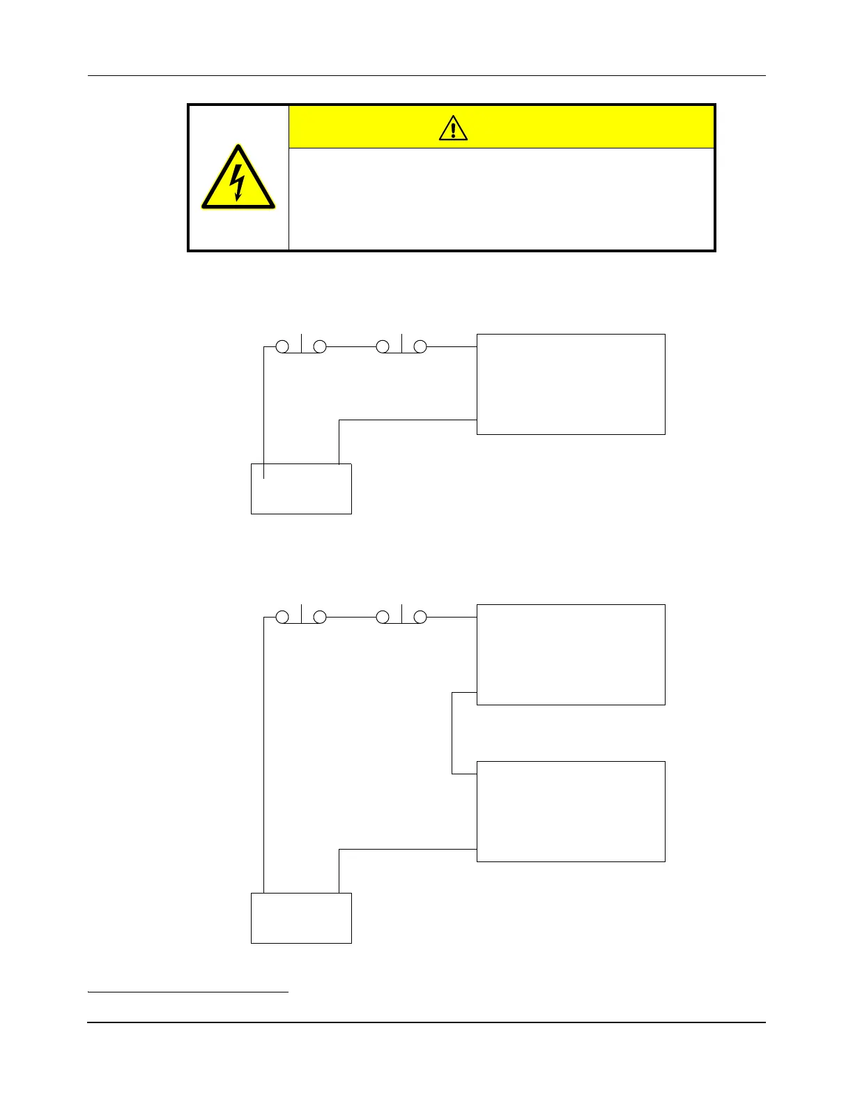
Figure 3-4: E-stop Wiring Diagram, Single Node Controller
Figure 3-5: E-stop Wiring Diagram, Multiple Node Controllers
*
CAUTION
Electrical Hazard
The E-stop only executes the actions that are described, it is
not the same as an EMO (Emergency Off), which removes
power to the transport system.
* In this configuration other digital I/O functions are not available.
Digital In
Digital In
E-stop NC-12 Node Controller
COM
-V +V
E-stop
+3–24V DC
Power Supply
E-stop NC-12 Node ControllerE-stop
NC-12 Node Controller (8 max)
-V +V
+3–24V DC
Power Supply
Digital In
Digital In
COM
Digital In
Digital In
COM

 Loading...


