Installation
Node Controller Installation
90 MagneMotion
Rockwell Automation Publication MMI-UM013B-EN-P - April 2020
Mounting NC-E Node Controllers
Locate the NC-E close to the nodes it is responsible for to minimize the length of all wiring.
The node controller can be oriented in any direction that is required, make sure the service and
exclusion zones that are identified in Figure 4-4 on page 57 are maintained. Typical mounting
methods for the NC-E use either DIN Rail Mounting or Surface Mounting.
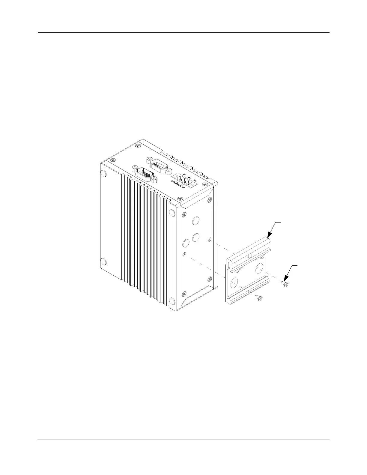
DIN Rail Mounting
The NC-E can be mounted to a DIN Rail by attaching the optional DIN rail mounting bracket
as shown in Figure 5-4.
Figure 5-4: NC-E Node Controller DIN Rail Mounting
1. Remove the hole plugs from the back of the node controller.
2. Install the DIN mounting bracket onto the node controller with the two supplied M4
flat head screws. Apply Loctite 243 to the screws and tighten to 1.1 N•m [10 in•lb].
NOTE: The Loctite must cure for 2 hours at 22° C [72° F] before using the transport
system.
3. Clip the node controller onto the DIN rail in the appropriate location. Make sure that
the service and exclusion zones are maintained.
4. Install cable management as required to secure the cables that are connected to the
node controller.

 Loading...


