8. MAINTENANCE
8 - 24
8.3 Switching of Velocity Loop Proportional Gain Using
Rotary Switch
8.3.1 Overview
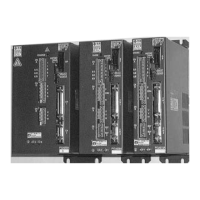
The PY or PY2 amplifier allows for easy switching of the velocity loop gain with its 8-position rotary switch
located on the front of the amplifier.
8.3.2 Setting Procedure
Set the slide switch on the front of the amplifier to GAIN. Then, set the following parameters.
Operator
Mode0-12 Velocity loop proportional gain add value (KvpA)
This parameter sets a weight per rotary switch 1.
The following shows the velocity loop gain actually set:
Kvp + (KvpA × RSW) or Kvp 2 + (KvpA × RSW).
Where, RSW is a rotary switch position.
You can check the Kvp actually set on the Kvp monitor (KvpM) for operator mode5-14.
Switching of Gain Using External Input Signal
Using external input signal (CN1-36 pin or 35 pin), this function performs switching of the position loop gain,
velocity loop proportional gain and velocity loop integral time constant.
Input signal OFF : Kp, Kvp and Tvi are valid.
Input signal ON : Kp2, Kvp2 and Tvi2 are valid.
This function is enabled when the parameter servo function select (Mode 4, Page 2) is set to "Gain_sel".
The Func3 bit6 parameter is used for selecting the CN1 input signal (0: 36 pin and 1: 35 pin).
Note 1: There is a 2 msec maximum time lag between switching of the input signal and that of the gain.
Note 2: The gain automatically set by the test mode servo tuning function is set at Kp, Kvp, Tvi and ILPF
irrespective of the above selection.
Note that setting the slide switch to HISTORY clears your setting and returns to the original
one.

 Loading...