3. SERVO SYSTEM CONFIGURATION
3-4
CHARGE
POWER
CN
1
2
CNA
CNB
CND
CNC
CN
r
t
R
S
T
P
Y
U
V
W
RDY
1
2
RDY
PY2A015
1
2
3
4
5
6
7
8
9
10
11
12
13
OP
14
SELECT
POWER
N
OP
SELECT
POWER
RDY
2
RDY
1
PY2E015
CN
2
CNC
CNB
CND
CHA
W
V
U
N
CN
1
11
Y
P
T
S
R
r
t
CHARGE
POWER
6
5
4
13
12
3
2
1
10
9
8
7
14
3.3.2 PY2E015/030
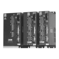
Fig. 3-4 Front View of Servo Amplifier
(PY2E015A1)
2 Control and main power supply (CNA)
Connect the control power supply (100 VAC,
single-phase) to r and t, and the main power supply (100
VAC, single-phase) to R and T.
Same as 1 and 3 to 14, 200 VAC input type.
(Refer to 3.3.1 PY2A015/030.)
14 Maintenance mode switch
• Be sure to set this switch to the normal mode for
operation (set it to the left when viewed from the front of
the amplifier).
• Never change the setting of this switch. If it is set to
the maintenance mode, the system will malfunction.
The 15 A and 30 A capacity amplifiers have different
dimensions (width).

 Loading...