3. SERVO SYSTEM CONFIGURATION
3-5
CHARGE
CN
1
2
CNA
CNB
CND
CNC
CN
r
t
R
S
T
Y
U
V
W
RDY
1
2
RDY
PY2A050
1
2
3
4
5
6
7
8
9
10
11
12
13
OP
14
SELECT
POWER
N
X
P
PY2A050
CNC
6
5
RDY
2
RDY
1
CN
2
CNB
W
V
12
13
4
U
CN
1
Y
X
Y
P
CND
3
POWER
SELECT
OP
2
1
T
S
R
t
r
CNA
10
11
8
9
CHARGE
7
14
3.3.3 PY2A050
3 Regenerative resistor connecting terminal
(CND)
When a built-in regenerative resistor is
used, use it at the settings made on
shipment (i.e. short-circuit the P and X
terminals using a short-circuit bar).
When an external regenerative resistor is
used, remove the short-circuit bar from
across the P and X terminals and install a
regenerative resistor between the P and Y
terminals.
Same as 1, 2 and 4 to 14, PY2A015/030.
(Refer to 3.3.1 PY2A015/030.)
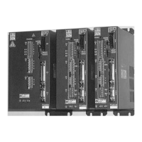
Fig. 3-5 Front View of Servo Amplifier
(PY2A050A4)
14 Maintenance mode switch
• Be sure to set this switch to the normal
mode for operation (set it to the left when
viewed from the front of the amplifier.)
• Never change the setting of this switch. If it
is set to the maintenance mode, the system
will malfunction.

 Loading...