14 Cubis
®
MCE Operating Instructions
Operating Concept
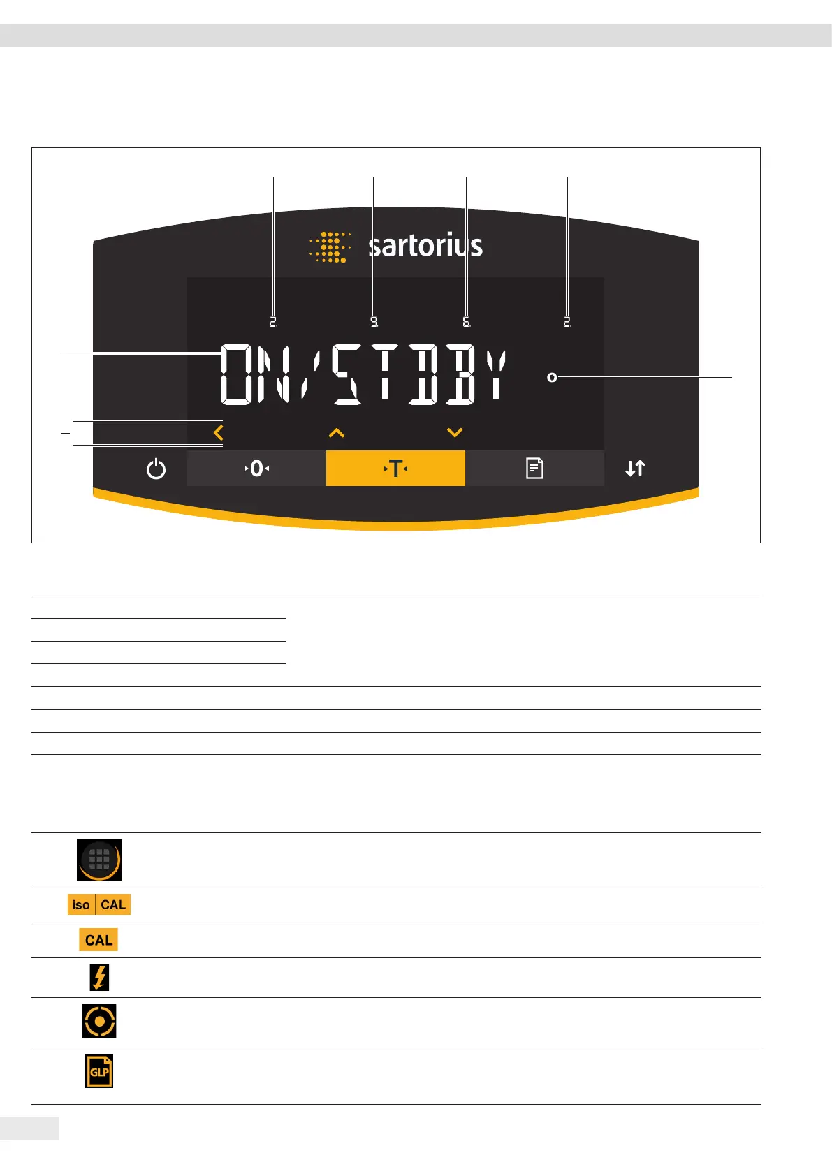
4.2 Operating Display in the Menu
1 2 3 4
5
7
6
Fig. 2: Operating display in the menu (example)
Pos. Designation Description
1 Position in the 1st menu level Shows the position of the displayed menu or configuration value in up to 4 menu
levels.
2 Position in the 2nd menu level
3 Position in the 3rd menu level
4 Position in the 4th menu level
5 [Computed values] display Note on the set menu item
6 Operating area
7 Name of the menu or setting
4.3 Buttons and Keys on the Operating Display
Pos. Symbol Designation Description
1
[Menu] button When the button is pressed: The settings menu opens.
If the button is held down: It switches to version display.
2
[isoCAL] button Starts the isoCAL function.
3
[Adjust] button Starts the set calibration and adjustment function.
4
[Ionizer] button Starts an ionization process.
5
[Leveling] button Starts a leveling process.
6
[GLP] button − Exits the GLP printout and starts printing the GLP footer.
− If the “Net-total”, “Totalizing”, or “Statistics” application is active: Prints and
deletes the saved values and exits the application.
 Loading...