Section 7: Replacement Procedures
CG4 Series Service Manual Page 7-13
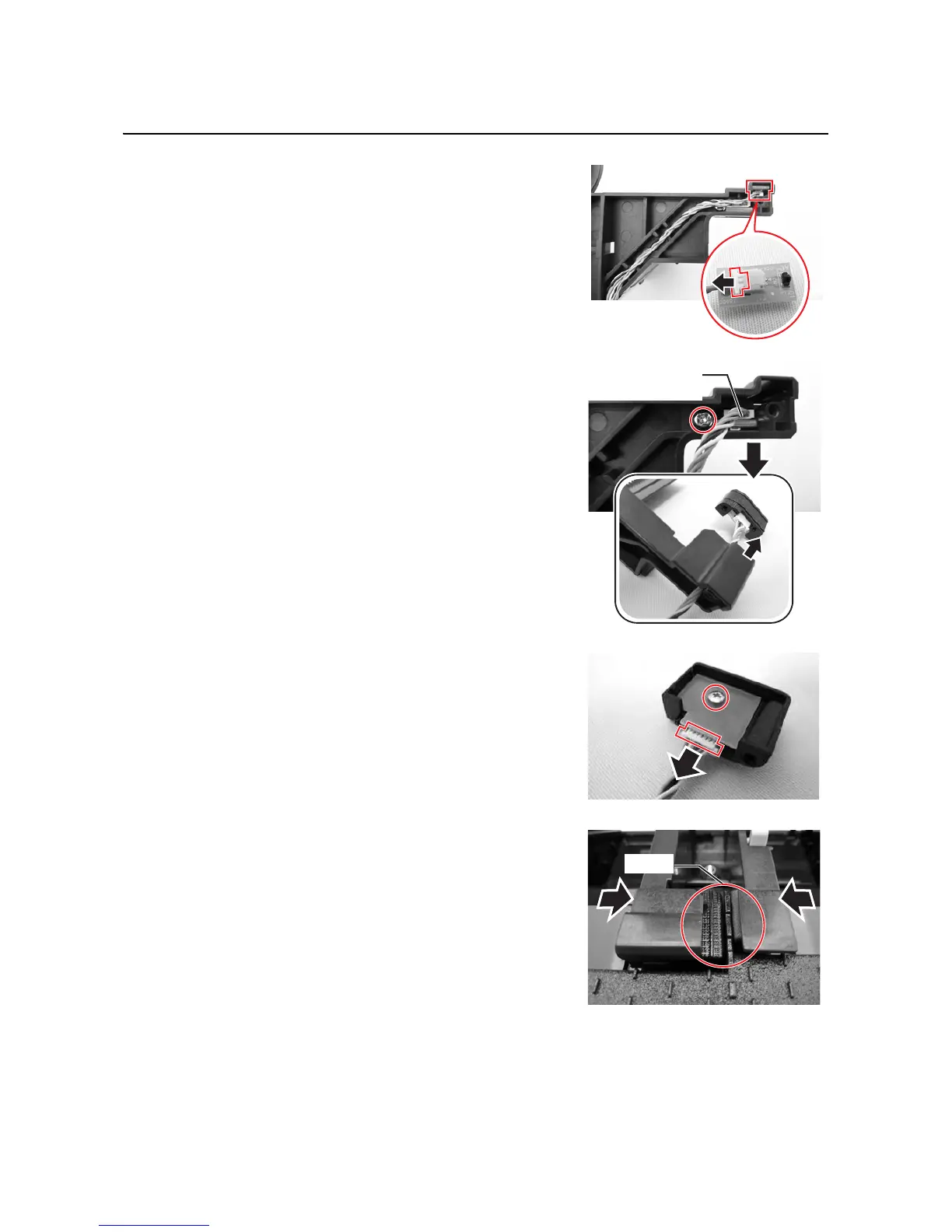
7.9 I-MARK/GAP SENSOR REPLACEMENT (cont’d)
8.
Remove the Upper Gap sensor board as indicated and
disconnect the attached
cable connector. Replace the new
Upper Gap sensor board.
9. Remove the screw (circled) securing the I-Mark/Gap
sensor board assy
to the left Media guide.
10.From the underside of the I-Mark/Gap sensor board assy,
remove the
screw (circled) securing the sensor cover to
the
I-Mark/Gap sensor board.
11.Disconnect the cable connector and replace the new I-
Mark/Gap sensor board
and follow the above steps in
reverse sequence, to reassemble the parts.
Notes:
• When fixing the Media guides back to printer, place the
Media guides separately on both sides with the maxi-
mum width. Then insert the shaft back in position, place
the
Media guide gear interlock with the guides and fix
them in position with the
washer faced screw.
• Ensure that there is no gap in between the
media
guides
when the media guides are adjusted to mini-
mum as shown.
12.After replacement, perform I-Mark/Gap sensor adjustment.
Refer to
Section 4.13 Factory Adjustment Mode.

 Loading...