Section 6: Checks and Adjustment Procedures
CG4 Series Service Manual Page 6-3
6.1 CHECKING THE POWER SUPPLY (cont’d)
Diagnosis and Remedy:
If the measurement at Test Point 5A could not meet the +19.0 V criteria, turn off the printer and remove the
power cable from the connector. Then, connect the probe to
Point F [+] and Point G [-] on the DC board to
measure the voltage of power source itself.
• When the power source itself still does not meet the +19.0 V criteria, replace the power adapter.
• When the power source itself complies with the specified value, replace the
MAIN PCB. Please refer to
Section 7.5 Main Circuit Board Replacement in this manual for instructions on replacement.
6.2 AUTOMATIC ADJUSTMENT OF I-MARK AND GAP SENSOR OUTPUTS
The I-Mark sensor adjustment regulates reflecting ability for media referencing and the GAP sensor
adjustment regulates penetrating ability for media referencing.
The CG4 Series printer features an automatic adjustment of I-Mark and GAP sensor outputs for optimum
performance. This feature can be activated in the Factory Adjustment mode. Please refer to
Section 4.13
Factory Adjustment Mode
for detailed procedures.
Diagnosis and Remedy:
From the third print-out of the Test printing, check the sensor level. The sensor output level for optimum
performance is as follows.
If the I-Mark or GAP sensor does not perform correctly, even after the adjustment of I-Mark and GAP sensor
automatically, replace the sensor board as describe in
Section 7.9 I-Mark/Gap Sensor Replacement.
6.3 SENSOR CHECKS
6.3.1 Ribbon End Sensor Check
(Only for CG408 TT and CG412 TT Thermal transfer printer)
1.
Press POWER button to turn on the printer.
2. Make sure the ribbon end error occurs when you press the FEED/LINE button while no ribbon is loaded.
ERROR indicator should display red.
3. If no error is indicated for above specified operations, check the connector connection. If there is nothing
wrong with the connection, the sensor needs to be replaced.
Refer to
Section 7.10 Ribbon End Sensor Replacement of this manual for Ribbon Sensor Replacement
instructions.
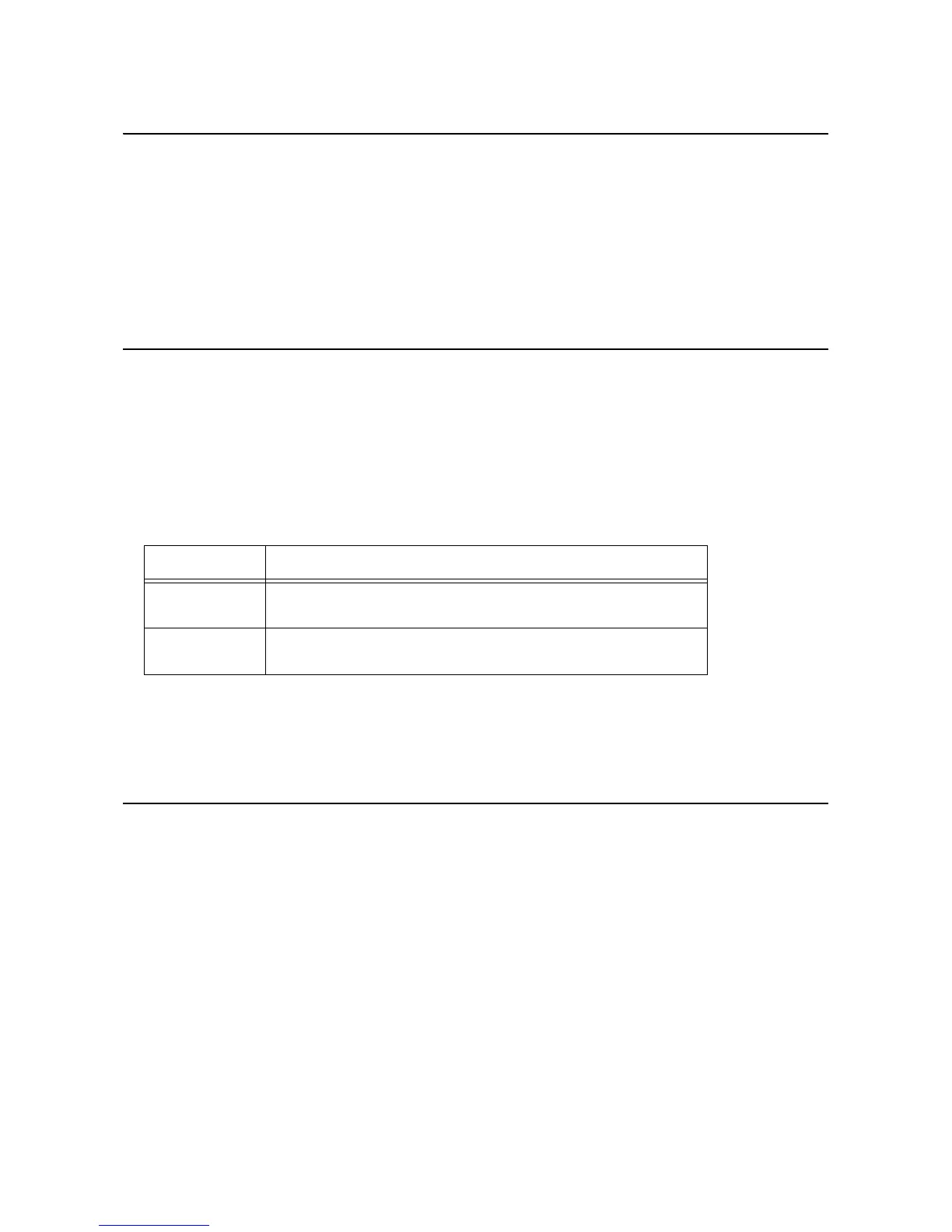
Sensor Sensor output level
I-Mark (MIN) 1.5V or below.
The difference between (MAX) and (MIN) must be 1.0V or more.
Gap (MIN) 1.5V or below.
The difference between (MAX) and (MIN) must be 1.0V or more.
 Loading...