Section 7: Replacement Procedures
CG4 Series Service Manual Page 7-17
7.13 CUTTER KIT/ BOARD/UNIT REPLACEMENT (OPTIONAL)
This section covers the basic mechanical procedures for replacement of the whole Cutter Kit or just the Cutter
board or Cutter unit.
Before replacement, check the cutter counter by printing a Factory test print. Please refer to Section for
details.
7.13.1 Cutter kit Replacement
1.
Remove the Bottom Housing Cover as explained in the
earlier
Section 7.3 Removal of the Bottom Housing
cover
.
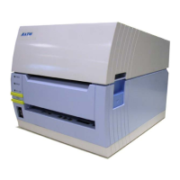
2. Disconnect the Cutter kit’s cable from the OPTION
connector on the MAIN PCB.
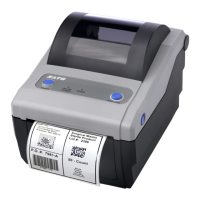
3. From the base of the Cutter kit, remove a screw (circled)
as shown.
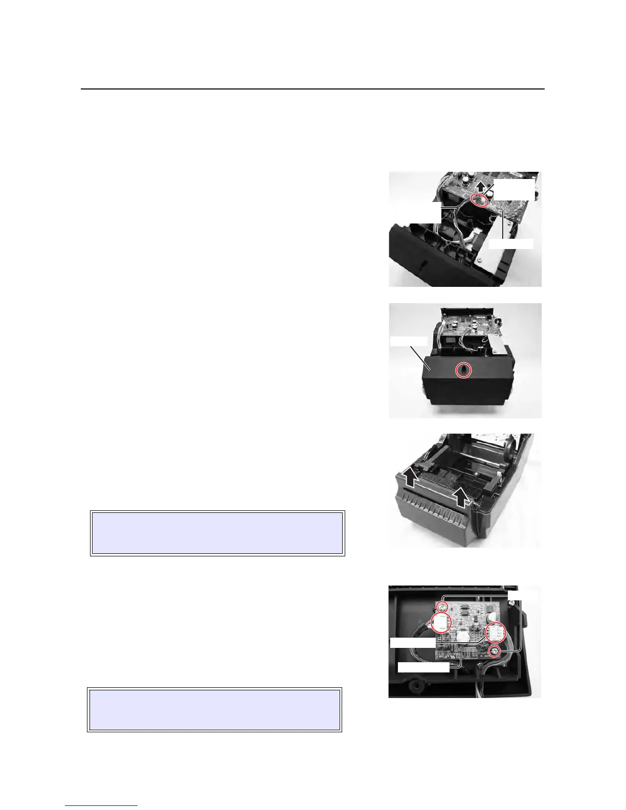
4. Turn over the printer in upright position, open the Top cover
and remove the
Cutter kit by lifting it upward.
5. Replace the new Cutter kit and follow the above steps in
reverse sequence, to reassemble the parts.
Continue the following steps if you required to replace the
Cutter board.
7.13.2 Cutter board Replacement
6.
From the circuit board side of the Cutter kit, remove two
screws (circled) securing the Cutter board to the Cutter
kit assembly
and disconnect the two cable connectors
from the defective
Cutter board.
7. Replace the new Cutter board and follow the above steps
in reverse sequence, to reassemble the parts.
Continue the following steps if you required to replace the
Cutter unit.
CAUTION:
Ensure that no cables are pinched between parts when
you are installing the
cutter kit to the printer.
CAUTION:
Ensure that no cables are pinched between parts when
you are installing the
cutter board to the printer.
 Loading...