Section 6: Checks and Adjustment Procedures
Page 6-2
CG4 Series Service Manual
6.1 CHECKING THE POWER SUPPLY
This checking procedure enables checking various direct current voltages of the MAIN Printed Circuit Board
(PCB). These checking activities require the use of a multimeter.
1. Switch off the printer.
2. Remove the Bottom Housing Cover as explained in Section 7.3 Removal of the Bottom Housing
cover
.
3. Set the multimeter to Direct Current Voltage mode.
4. Turn the printer On.
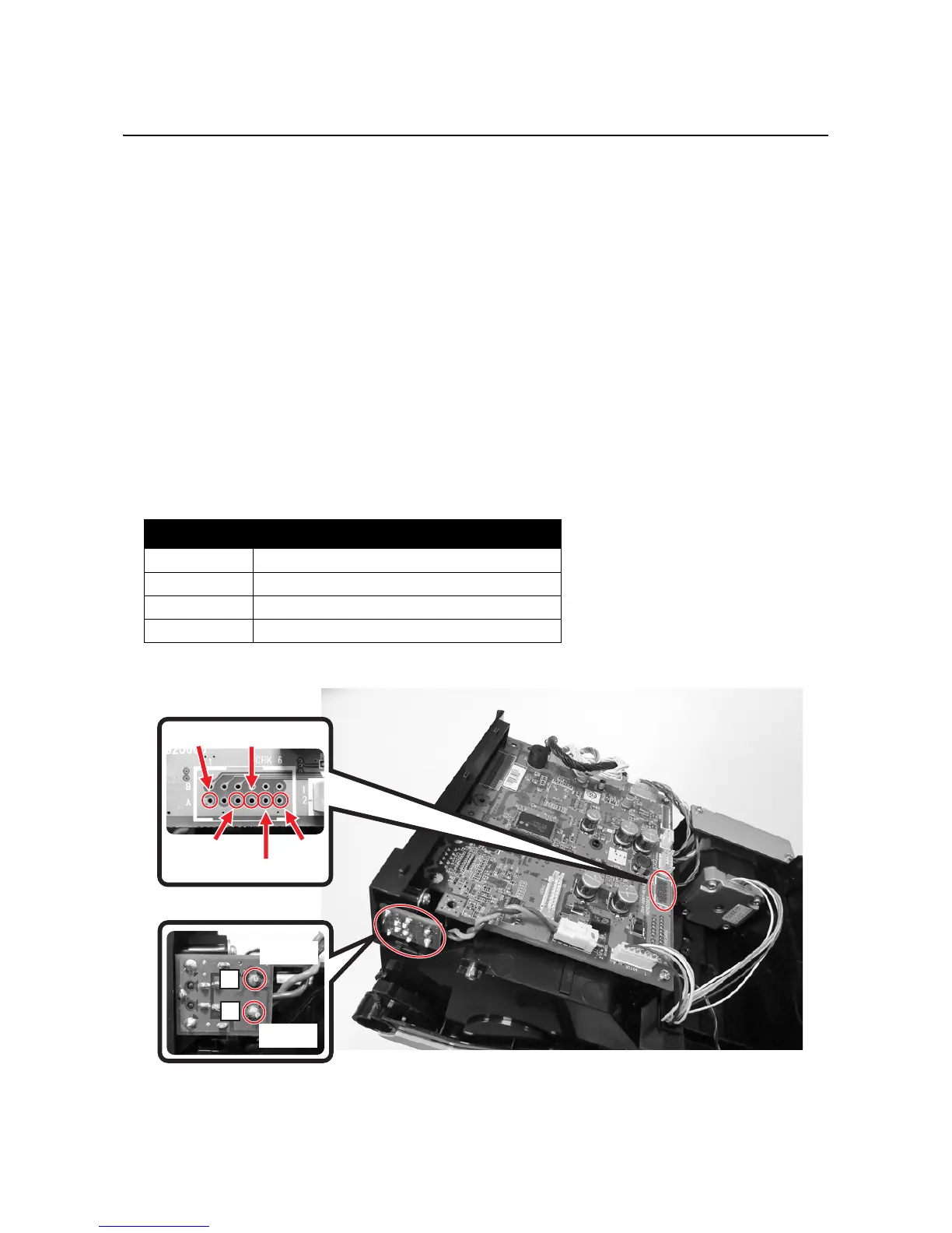
5. Keep placing the [-] probe of the multimeter at the 1A(GND) test point on the MAIN PCB for the following
measurement.
6. Place [+] probe at Test Point 5A, and then measure at +19.0 V.
7. Place [+] probe at Test Point 3A, and then measure at +5.0 V.
8. Place [+] probe at Test Point 4A, and then measure at +3.3 V.
9. Place [+] probe at Test Point 6A, and then measure at +1.8 V.
10.Turn the printer off.
Table of normal performance values:
+1.8 V +1.7 V to +1.9 V (Test Point 6A)
+3.3 V +3.1 V to +3.5 V (Test Point 4A)
+5.0 V +4.8 V to +5.2 V (Test Point 3A)
+19.0 V +18.0 V to +20.0 V (Test Point 5A)

 Loading...