Section 3: Interface Specifications
CG4 Series Service Manual Page 3-9
3.3 IEEE 1284 PARALLEL INTERFACE (cont’d)
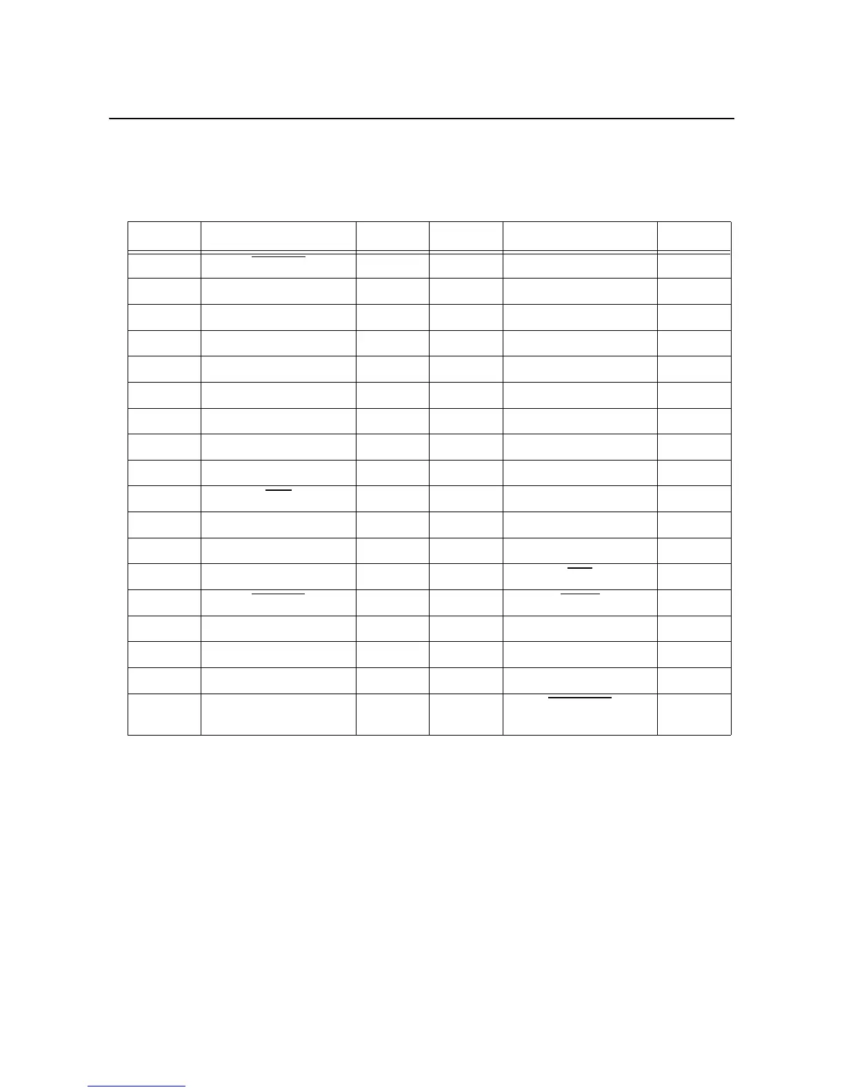
3.3.2 Pin Assignments
Pin assignment of each signal for the Centronics standard (Compatible Mode) is as follows.
Note that the connection of the IEEE1284standard complies with the IEEE1284-B standard.
PIN No. Signal I/O PIN No. Signal I/O
1STROBE
Input 19 STROBE-RETURN
2 DATA 1 Input 20 DATA 1-RETURN
3 DATA 2 Input 21 DATA 2-RETURN
4 DATA 3 Input 22 DATA 3-RETURN
5 DATA 4 Input 23 DATA 4-RETURN
6 DATA 5 Input 24 DATA 5-RETURN
7 DATA 6 Input 25 DATA 6-RETURN
8 DATA 7 Input 26 DATA 7-RETURN
9 DATA 8 Input 27 DATA 8-RETURN
10 ACK
Output 28 ACK -RETURN
11 BUSY Output 29 BUSY -RETURN
12 PE Output 30 PE -RETURN
13 SELECT Output 31 INIT
Input
14 AUTOFD
Input 32 FAULT Output
15 33
16 LOGIC GND 34
17 CHASSIS GND 35
18 PERIPHERAL LOGIC
HIGH
Output 36 SELECTIN
Input
 Loading...