Section 7: Replacement Procedures
CG4 Series Service Manual Page 7-3
7.1 PRINT HEAD REPLACEMENT (cont’d)
7.1.2 Print Head Replacement (For CG408 TT and CG412 TT Thermal transfer printer)
1.
Ensure the printer is turned off, and remove the power
cable.
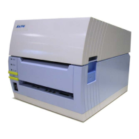
2. Lift the Top Cover.
3. Pull the lever on the middle of the ribbon unit downward to
pull out the
ribbon unit. Then, simply let down the ribbon
unit
. There is a stopper midway through its movement
range that will prevent the ribbon unit from snapping down.
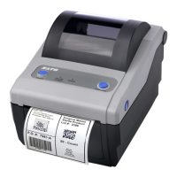
4. On the right side of the ribbon unit, slide the print head
release lever
to unlock the print head assembly. Move
the whole
print head assembly downward.
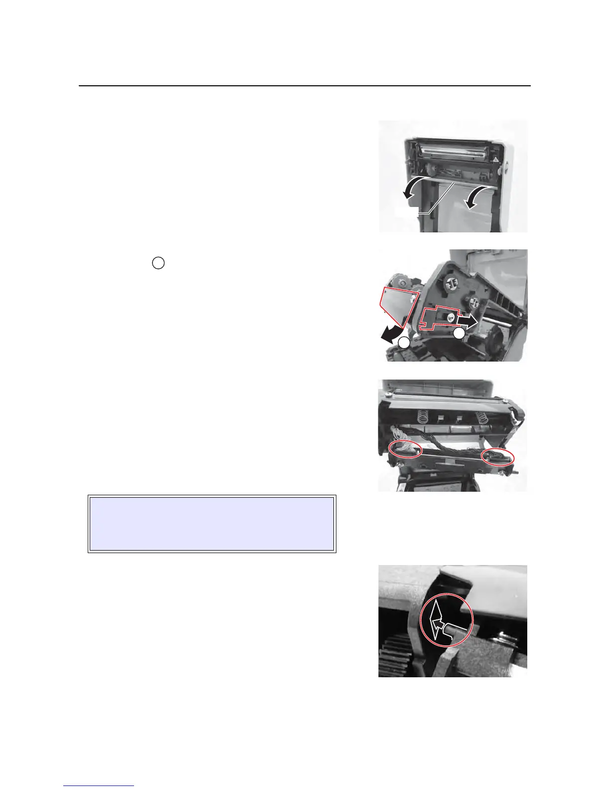
5. The cable connectors (circled) at the rear of the print head
is now exposed. Pull the
print head downward, then gently
disconnect the defective
print head from the cable connec-
tors.
6. Carefully connect the cable connectors to a replacement
print head. The white cable should be connected to the left
connector
while black cable should be connected to the
right connector. The connectors are keyed so that they can
only be inserted in the correct orientation.
7. Insert the left shaft of the new print head assembly into
the hole on the left side of printer (see circled area).
CAUTION:
EXCERCISE CARE WHEN INSTALLING THE
PRINT HEAD TO ENSURE THAT ITS ELEMENTS
ARE NOT DAMAGED DURING INSTALLATION.
 Loading...