EQJW145:
Heating controller
Communication
functions
7010015003 A
73
© Fr. Sauter AG
For the other control loops or the program for the pilot timer/circulation pump,
the same logic applies, but the register numbers are 100 higher in each case.
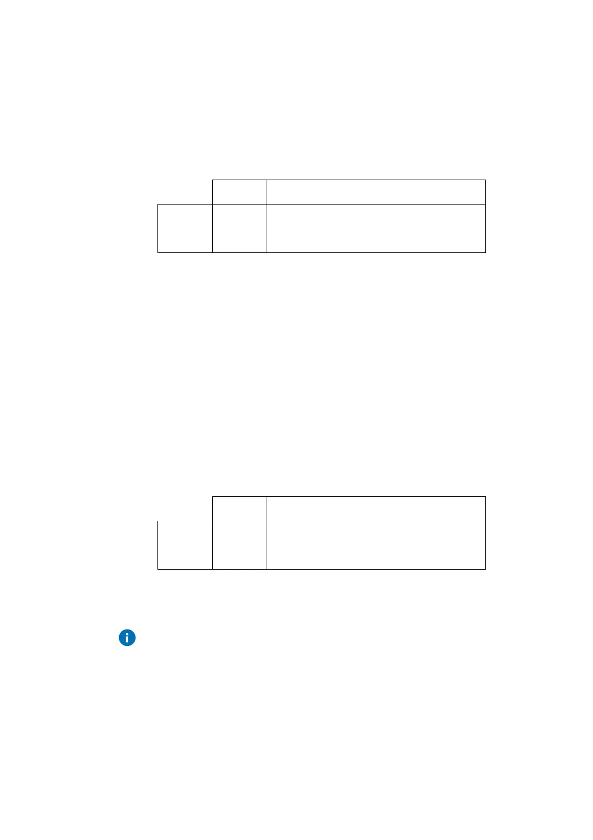
Every possible switching command has its own holding register (a 16-bit
value) that can be read or written. For the contents of the register, the
following applies:
Command Time
Numerical
value
(decimal)
3 0 7 3 0 30730
1 = Stand-by mode
2 = Reduced mode
3 = Normal mode
To change the factory setting for the first switching command (nominal mode,
every day from 6:00 hrs) to 7:30 hrs, you have to write a value of 30730
(instead of the current 30600) in register 42042.
Read and write calendar programme of switching commands via
Modbus
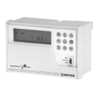
The 20 holding registers from 42500 to 42519 contain the 20 possible
switching commands for the calendar switching programme. For the contents
of the register, the following applies:
Command Date
Numerical
value
(decimal)
1 3 1 1 2 13112
1 = Stand-by mode
2 = Reduced mode
3 = Normal mode
Important notes on the weekly and calendar switching programs:
All the registers for unused switching commands should contain the
value 0.
The switching commands should be entered in the chronological order of
time/date. The first command of a day/year should, therefore, be under
'Command1'.
Examples