2 Installation
2--9
F--9999--8 Build 8 Issue 1
DANGER: ELECTRICAL CONNECTIONS
MUST BE MADE BY A QUALIFIED
ELECTRICIAN FAMILIAR WITH
APPLICABLE ELECTRICAL CODES
AND REGULATIONS. ELECTRICAL
CONNECTIONS MUST THEN BE MADE
ONLY AFTER REVIEWING AND
UNDERSTANDING THE ELECTRICAL
SCHEMATICS SUPPLIED WITH
MACHINE AND SAFETY SECTION OF
THIS MANUAL, FAILURE TO EXERCISE
NECESSARY SAFETY PRECAUTIONS
CAN RESULT IN SERIOUS BODILY
INJURY OR DEATH.
WARNING!
2.2 Utility Connections
2.2.1 Electrical Connections
1. The machine requires No. 10, 3 wire cable
including ground for 220 volt, single phase
electrical power.
Note ! Electrical cables going to machine
should be routed overhead and be of
sufficient height to allow personnel to
travel around entire machine without
interference. The figure below shows
recommended installation
configuration.
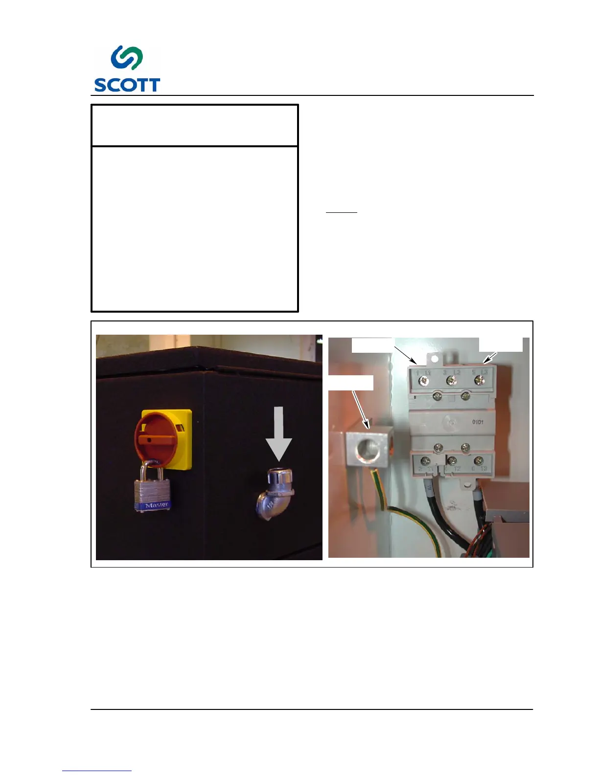
GROUND
TERMINAL
1L1
TERMINAL
5L3
TERMINAL
Fig. 2-12. Installation Wiring Route
2. Route main power electrical cable through the conduit opening in the back of the control cabinet.
3. Connect two “hot” leads onto terminals 1L1 and 5L3 on main power relay. Connect neutral lead to
ground terminal.