VB220
VB242
VB242
ASI
ASI1
ASI2
ASI3
ASI4
ASI5
ASI6
ASI1
ASI2
ASI3
ASI4
ASI5
ASI6
VB220
VB242
VB242
ASI
ASI1
ASI2
ASI3
ASI4
ASI5
ASI6
ASI1
ASI2
ASI3
ASI4
ASI5
ASI6
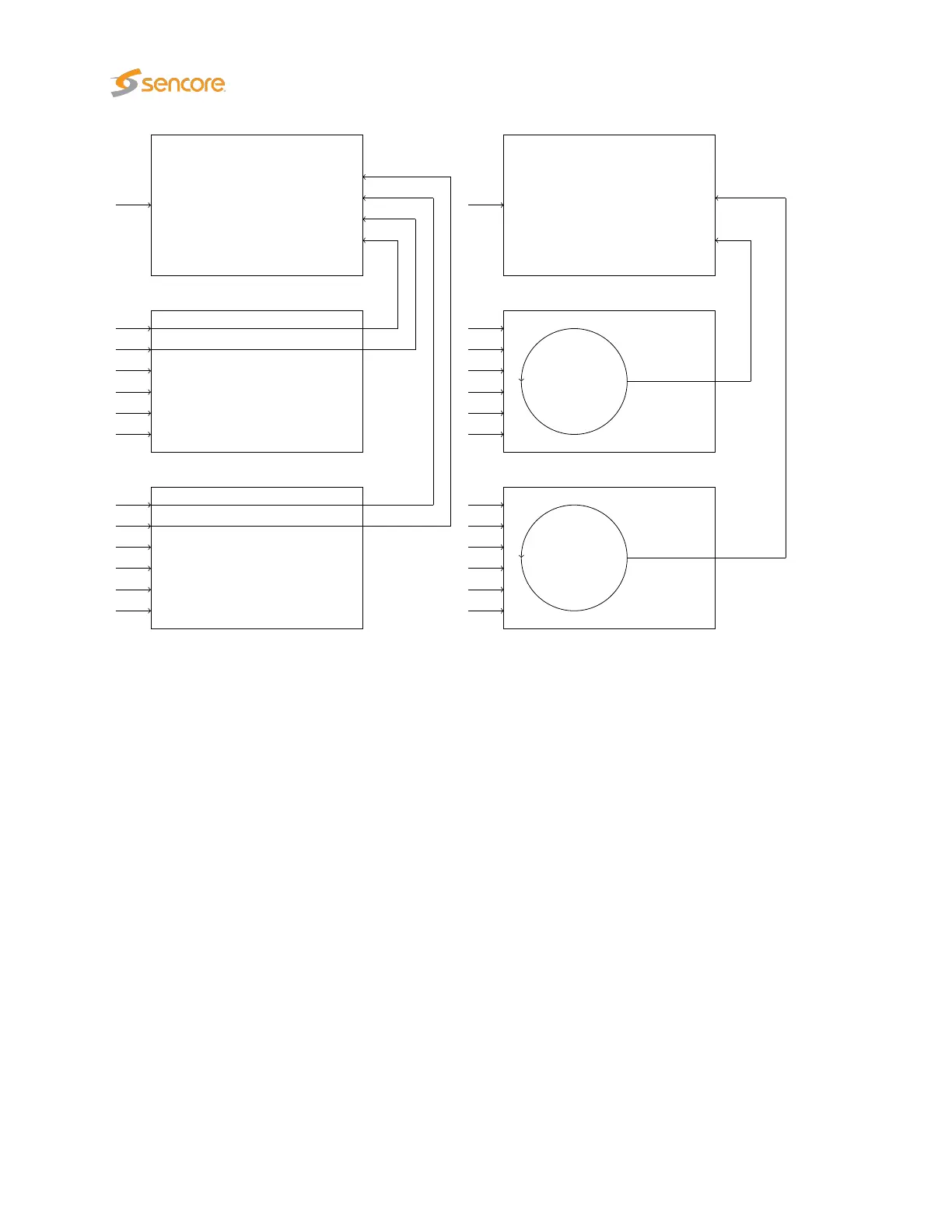
The figure above illustrates signal routing for two VB242 modules in one chassis, for continuous monitoring
mode and round-robin mode respectively. The circles represent round-robin functionality, where the ASI
inputs can be monitored sequentially. In continuous mode five ASI signals may be analyzed in parallel by
the probe module, whereas in round-robin mode three ASI signals are analyzed in parallel.
6.12 COFDM (VB252 Option Module for VB220)
The COFDM tab will be present in the graphical user interface provided that the probe chassis is equipped
with an optional COFDM demodulator module. The VB252 has two RF inputs per module. Each COFDM
tab represents an independent RF input.
COFDM1 is the leftmost input as seen from the front of the unit. There can be up to four COFDM tabs
(COFDM1 through to COFDM4) depending on card configuration and licenses.
For the VB252 one input is active by default and the second input can be activated through the SECOND-
RF-INPUT-OPTION license key.
Thumbnails for the RF demodulated services are accessed from the
ETR 290 — Services
and
Main —
Thumb overview views.
178 VB2xx GigE User’s Manual version 5.4