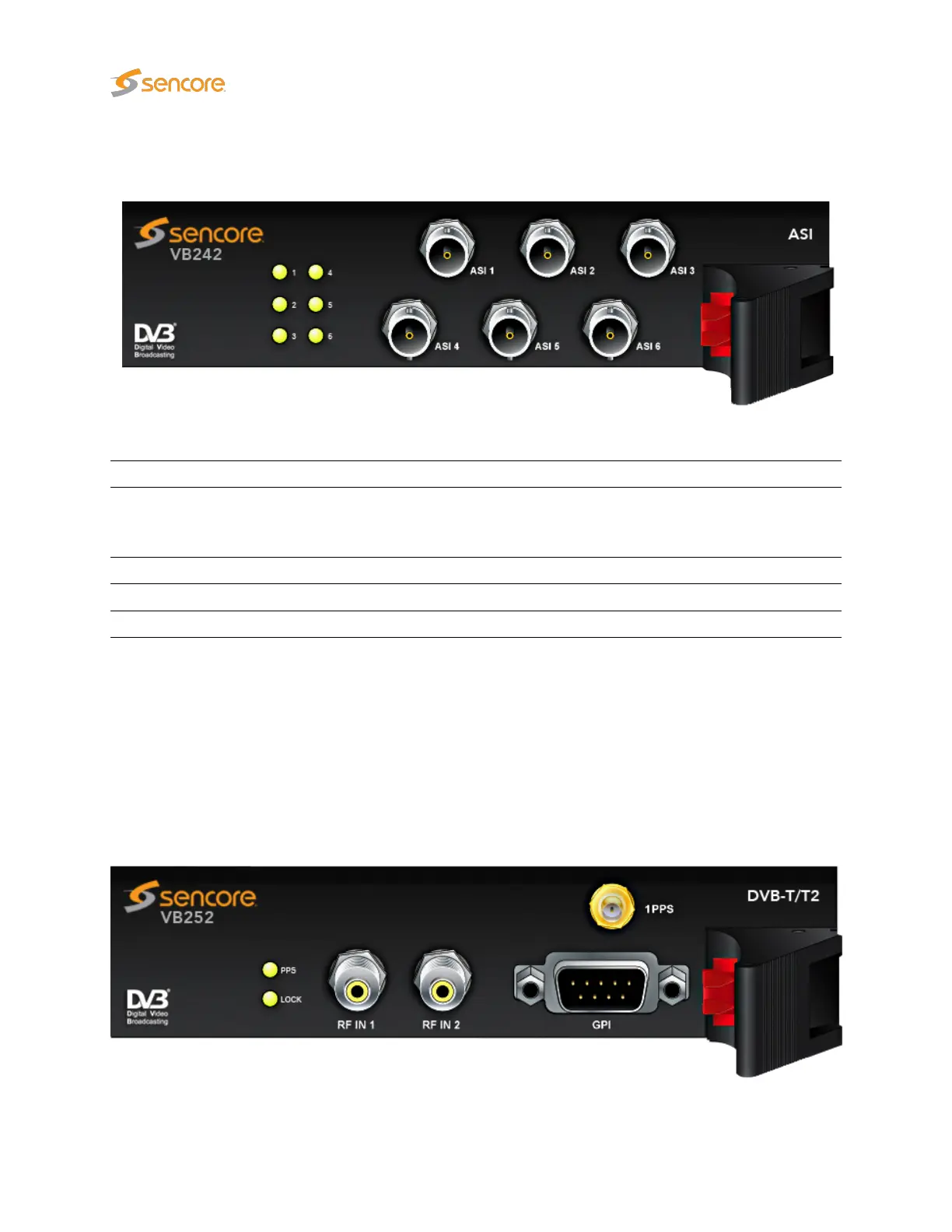
4.8.2 The VB242 ASI Input Module (VB220 option)
The VB242 module is equipped with the following connectors:
ASI 1 – 6 : ASI transport stream input – 75 ohm BNC female
For each ASI input an associated LED indicates current status:
GREEN: The associated ASI input is currently being monitored and there is ASI sync
RED: The associated ASI input is currently being monitored and there is not ASI sync
ORANGE: The associated ASI input is not currently being monitored
The VB242 module operates by default in continuous mode where the connectors ASI1 and ASI2 are
transmitted across the backplane of the chassis to the probe module for continuous analysis.
Alternatively the VB242 module can be configured through the web GUI to operate in round-robin mode
where the inputs ASI1 through to ASI6 are brought across the backplane one at a time for further analysis.
4.8.3 The VB252 COFDM Dual Demodulator Module (VB220 option)
26 VB2xx GigE User’s Manual version 5.4