58
Operating Instructions – Electronic Motor DRC.-..-SNI
5
Plug connectors
Electrical Installation
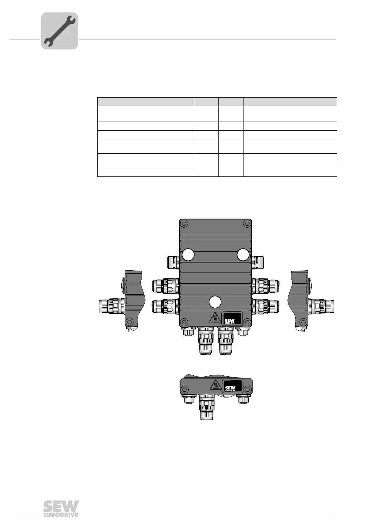
5.9.3 Plug connector positions
The following figure shows possible plug connector positions. A difference is made
between plug connectors with selectable position and plug connectors with fixed
position:
Plug connector Color Position Location
X5131: Digital inputs/outputs – As
required
X, 2 or 3,
not together with X1241_1, X1241_2
X5502: STO – IN Orange Fixed 3 (left)
X5503: STO – OUT Orange Fixed 3 (right)
X1241_1: AC 400 V connection with SNI
1)
1) Plug connector X1241_1 is also available separately (i.e. without plug connector X1241_2).
Red As
required
X, 2 or 3, not together with X5131
X1241_2: AC 400 V connection with SNI Red As
required
X, 2 or 3, not together with X5131
[1] Pressure compensation
2)
2) Only in conjunction with the optional design for use in wet areas (with MOVIGEAR
®
) / ASEPTIC design
(with DRC).
– Fixed Depends on mounting position
9007201923558283
[1]
X5502
X1241_1
X1241_1 X1241_1
X1241_2
X1241_2
X1241_2
X5503
X5131X5131
X5131
[1]
X
2
3